background image

Page


12 from


13

940851000

_09_001

Installation procedure

Installation procedure

Fig

. 1

Fig

. 2

Fig

. 3

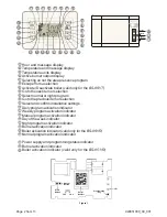
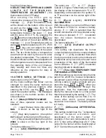
To install the devices BS-850/T or BS-851/T

insert a flat blade screwdriver in the slot as shown 

in (Fig. 1). Press and lift the front cover.
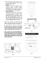
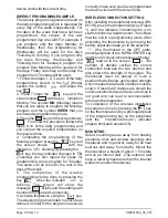
Remove the retaining screws and remove the plastic cover that contains the keys (Fig

.


2).

Use the supplied mount accessories to mount the unit according to the diagram of page 11. 
Install the base, align it using the built in vial and tighten the screw to secure it.
Reinstall the plastic containing the keypad with care and fasten the screws with a maximum 
torque of 

0,5 

Nm.

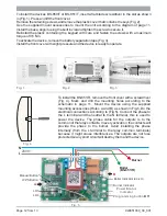
To activate the device, remove the battery separation tape

 (

Fig

.


3).

Install the front cover with slight pressure and the device is ready to operate

.

Fig

. 4

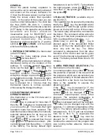
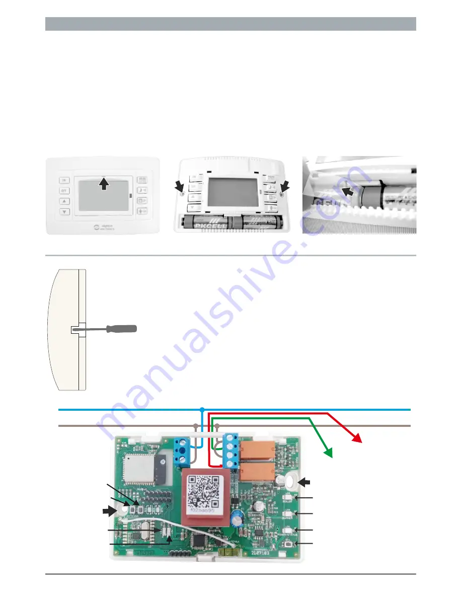
To install the BS-851/R

remove the front cover


with a screwdriver 

(

Fig

.


4).

  Mark  and  drill  the  mounting  holes  according  to  the 

schematic  in  page  11.  Mount  the  device  using  the  supplied 
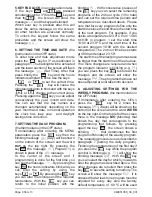
mounting accessories (Holes  A and B)  as shown in Fig.5. Do the 
electrical connections according to (Fig.5). Connect the phase to 
the L terminal and the neutral to the N terminal, this is used to 
power  the  device.  The  phase  cable  for  the  outputs  is  to  the 
common of the relay contacts. In every activation, the contacts will 
provide  the  phase  to  the  burner.  Avoid  installing  the  phase 
internally  (from  the  L  terminal  to  the  relay  common  terminals) 
because it might cause interferences. The outputs are not fuse 
protected so any short circuit will destroy them and the device.

N

L

230V~

Boiler Indicator


(BS-851)

LD5

LD4

Boiler
(BS-851/R)

Burner

Fig

. 5

Burner Indicator

A

B

WPS Button

Manual Button

Power/Status

Indicator

Programming button 

BT1

Содержание BS-850/T

Страница 1: ...851 T BS 850 R BS 851 R Only for BS 851 R CONTROL AND INDICATIOR DESCRIPTION Thermostat activation Thermostat deactivation Increase value Decrease value Presence indicator Thermostat active Thermostat...

Страница 2: ...r selection Select normal or night program Go to the previous item or selection Select and confirm installation settings Daily program activation indicator Weekly program activation indicator Manual p...

Страница 3: ...serial number located inside the receiver or scan the QR Code on the included card Otherwise you can insert the serial number by typing the 32digit on the included card Figure 2 Figure 3 2 Figure 4 CO...

Страница 4: ...Figure 1 on the thermostat and at the end the SEND icon from the application Figure 7 When they connect the LD4 must blink every 2 seconds while the LD5 must be off which means there is internet conn...

Страница 5: ...of the program that was running before absence mode was selected GENERAL When the plastic battery separator is removed the unit is automatically activated and shows all the screen indicators for 1 the...

Страница 6: ...With consecutive presses of the key you can select the remaining programs of the 24 hour cycle 10 in total and can set the required time periods and temperatures as described above Please note that fo...

Страница 7: ...he top right of the screen The factory default is Unit TEMPERATURE UNIT The option are or Degree Celsius Degree Fahrenheit and regard the display of the temperature in C or F Depending on the selectio...

Страница 8: ...t it will not permit it to operate The battery life time has been design to be approximately one year Factors that influence the battery life are prolong use of the keyboard with the backlight active...

Страница 9: ...screen shows with the Mode blinking 4 Press the key and the starts to blink With the keys and select the operation mode Day daily program 5 Press the key to return to the previous screen with the bli...

Страница 10: ...blinking The screen will show the message briefly and the settings will be stored in to the devices memory 6 Activate the device using the key The weekly program will start to execute as defined In or...

Страница 11: ...en will blink The interruption of the mains voltage causes the interruption of communication between the two devices When the voltage is restored the peripheral device receiver activates the outputs a...

Страница 12: ...is ready to operate Fig 4 To install the BS 851 R remove the front cover with a screwdriver Fig 4 Mark and drill the mounting holes according to the schematic in page 11 Mount the device using the sup...

Страница 13: ...to repair or to replace the returned goods and to or not charge the buyer depending on the reason of defection Olympia Electronics reserves the right to charge or not the buyer the transportation cost...

Отзывы: