background image

Page


10 from


13

940851000

_09_001

device clock with the correct time.

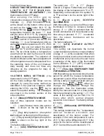
WEEKLY PROGRAMING EXAMPLE.

The weekly program in general is based on 
the daily programming which is repeated for 
every day of the week independently. For 
the  days  of  the  week  that  have  not  been 
programmed,  the  values  of  the  last 
programmed day are valid.


For example, if 

you  program  only  the  days  Monday  to 
Wednesday,  then  the  programming  for 
Wednesday  will  be  used  for  the  days 
Thursday  to  Sunday.


If  you  program  only 

the  days  Monday,  Wednesday  and 
Thursday  then  for Tuesday’s  program  the 
program from Monday will be used and for 
the days Friday, Saturday and Sunday the 
program from Thursday will be used.

1. 

Follow the steps 

1, 2

,

 3

,


and

 4 

of the daily 

programming.  Select  in  the        (Mode) 
section  the  setting              and  press  the             
key        .

2. 

Press 

times the                 key


and the 

screen shows          with the        indication 
blinking

The symbol


ΜΟ

 (

Monday) means 

that you are ready to program the Monday 
program  and  the  symbol 

WEEK 

that  you 

are in weekly programming mode.

3. Press the         key and the screen shows

       .  From now the procedure follows the 
steps  8-14  of  the  daily  programming  and 
you can set the required temperatures on 
the required time.

4.  Completing  the  programming  of  the 
Monday program press the                 key and 
the  screen  shows              with  the             
indication           blinking. By pressing the

       key, the day indicator changes to  

TU


(Τuesday)  you  can  repeat  the  steps  for 
programming a new program for Tuesday. 
The same can be done for the rest of the 
days of the week.

5.  The  completion  of  the  weekly 
programming can be done by pressing the 
key                 when the indicator                 is 
blinking.  The  screen  will  show  the       
message         briefly and the settings will 
be stored in to the devices memory.
6. Activate the device using the               key. 
The weekly program will start to execute as 
defined. In order for the program to execute 

correctly make sure you have programmed 
the device clock with the correct time. 

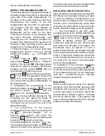
WIRELESS CONNECTION SETTING

After installing the peripheral received

 (

BS-

851/R)

,

 press the programming key (Figure 

1

until  the  indicator


POWER/STATUS  (LD1)


starts to blink in a rapid manner. This shows 
that the unit is in programming mode.


After 

activating  the  thermostat  by  removing  the 
battery separation tape

go to the selection


(

the  thermostat  in  the  OFF  state, 

prolonged press of the 


MENU/ENTER key 

and then 

22

 consecutive presses of the key

             lead us to the screen

               ). 

The 

number  of  dashes  verifies  the  correct 
connection  between  the  two  devices  and 
also shows the strength of the signal.


The 

thermostat  must  be  placed  in  such  a 
position that will allow good signal strength 
which means that at least 2 dashes must be 
shown. If less that 2 dashes are shown the 
communication between the two devices is 
not  good  and  can  lead  to  communication 
errors and bad operation.
To  completion  of  the  wireless  installation 
procedure is done by pressing the        key 
on the thermostat and by a prolonged press 
of the programming key on the peripheral 
until  the 


POWER/STATUS(LD1)

  indicator 

stops to blink and remains ON.

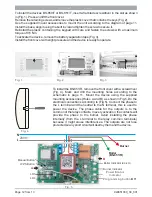
MOUNTING

Select mounting areas away from heating 
elements, door and window openings and 
fireplaces and in general, away for all heat 
sources  and  away  from  drafts.  Mount  the 
thermostat at a height of about 1.5 meters 
and on an interior wall 

 (

The external wall 

have a lower temperature than the internal 
wall and can affect the device

).

ESC

MENU

ENTER

ESC

ESC

ESC


Содержание BS-850/T

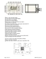
Страница 1: ...851 T BS 850 R BS 851 R Only for BS 851 R CONTROL AND INDICATIOR DESCRIPTION Thermostat activation Thermostat deactivation Increase value Decrease value Presence indicator Thermostat active Thermostat...

Страница 2: ...r selection Select normal or night program Go to the previous item or selection Select and confirm installation settings Daily program activation indicator Weekly program activation indicator Manual p...

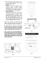
Страница 3: ...serial number located inside the receiver or scan the QR Code on the included card Otherwise you can insert the serial number by typing the 32digit on the included card Figure 2 Figure 3 2 Figure 4 CO...

Страница 4: ...Figure 1 on the thermostat and at the end the SEND icon from the application Figure 7 When they connect the LD4 must blink every 2 seconds while the LD5 must be off which means there is internet conn...

Страница 5: ...of the program that was running before absence mode was selected GENERAL When the plastic battery separator is removed the unit is automatically activated and shows all the screen indicators for 1 the...

Страница 6: ...With consecutive presses of the key you can select the remaining programs of the 24 hour cycle 10 in total and can set the required time periods and temperatures as described above Please note that fo...

Страница 7: ...he top right of the screen The factory default is Unit TEMPERATURE UNIT The option are or Degree Celsius Degree Fahrenheit and regard the display of the temperature in C or F Depending on the selectio...

Страница 8: ...t it will not permit it to operate The battery life time has been design to be approximately one year Factors that influence the battery life are prolong use of the keyboard with the backlight active...

Страница 9: ...screen shows with the Mode blinking 4 Press the key and the starts to blink With the keys and select the operation mode Day daily program 5 Press the key to return to the previous screen with the bli...

Страница 10: ...blinking The screen will show the message briefly and the settings will be stored in to the devices memory 6 Activate the device using the key The weekly program will start to execute as defined In or...

Страница 11: ...en will blink The interruption of the mains voltage causes the interruption of communication between the two devices When the voltage is restored the peripheral device receiver activates the outputs a...

Страница 12: ...is ready to operate Fig 4 To install the BS 851 R remove the front cover with a screwdriver Fig 4 Mark and drill the mounting holes according to the schematic in page 11 Mount the device using the sup...

Страница 13: ...to repair or to replace the returned goods and to or not charge the buyer depending on the reason of defection Olympia Electronics reserves the right to charge or not the buyer the transportation cost...

Отзывы: