


12
Minimum Vent Pipe Clearance
Wood and other combustible materials must not be
closer than 6” from any surface of single wall metal
vent pipe. Listed Type B vent pipe or other listed
venting systems shall be installed in accordance with
their listing.
Removing Existing Boiler From Common
Venting System
When an existing boiler is removed from common
venting system, common venting system is likely to be
too large for proper venting of appliances remaining
connected to it.
At time of removal of existing boiler, following steps
shall be followed with each appliance remaining
connected to the common venting system placed
in operation, while other appliances remaining
connected to common venting system are not in
operation.
1.
Seal any unused openings in the common venting
system.
2.
Visually inspect the venting system for proper size and
horizontal pitch and determine there is no blockage or
restriction, leakage, corrosion and other deficiencies
which could cause an unsafe condition.
3.
Insofar as is practical, close all building doors and
windows and all doors between the space in which the
appliances remaining connected to the common venting
system are located and other spaces of the building.
Turn on clothes dryers and any appliance not connected
to the common venting system. Turn on any exhaust
fans, such as range hoods and bathroom exhausts, so
they will operate at maximum speed. Do not operate a
summer exhaust fan. Close fireplace dampers.
4.
Place in operation the appliance being inspected. Follow
the lighting instructions. Adjust thermostat so appliance
will operate continuously.
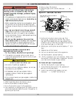
7 - CHIMNEY AND VENT PIPE CONNECTION
5.
Test for spillage at the draft hood relief opening after
5 minutes of main burner operation. Use the flame of
a match or candle, or smoke from a cigarette, cigar or
pipe.
6.
After it has been determined that each appliance
remaining connected to the common venting system
properly vents when tested as outlined above, return
doors, windows, exhaust fans, fireplace dampers and
any other gas-burning appliance to their previous
conditions of use.
7.
Any improper operation of the common venting system
should be corrected so the installation conforms with
the National Fuel gas Code, ANSI Z223.1/NFPA 54,
and/or the Natural Gas and Propane Installation Code,
CAN/CSA B149.1. When re-sizing any portion of the
common venting system, the common venting system
should be re-sized to approach the minimum size
determined using the appropriate tables in Chapter 13
of the National Fuel Gas Code, ANSI Z223.1/NFPA 54,
and/or the Natural Gas and Propane Installation Code,
CAN/CSA B149.1.
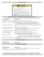
WARNING
Boiler and venting installations shall be performed
by a qualified expert and in accordance with the
appropriate manual. Installing or venting boiler
or other gas appliance with improper methods or
materials may result in serious injury or death due
to fire or to asphyxiation from poisonous gases such
as carbon monoxide with is odorless and invisible.
!
WARNING
Do not connect boiler to any portion of mechanical
draft system operating under positive pressure.
!


