21
Lean the heater against the wall so that it cannot
tilt forward.
The final fixing is made when the core bricks have
been installed and the heater has ‘settled’ some-
what.
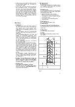
fig.15
•
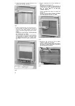
Off Peak supply for storage circuit
Feed the electrical supply cable through the right
conduit in the heater base and then forwards
through the strain relief. Secure the cable in the
strain relief using a 2 point pozidriver (fig.16a).
Connect the cables according to the wiring dia-
gram (wires N and L to the terminal block; earth
wire to the lower right of the plinth).
fig.16a
•
On Peak supply for convector circuit
Feed the electrical supply cable through the left
conduit in the heater base and then forwards
through the strain relief. Secure the cable in the
strain relief using a 2 point pozidriver (fig.16b).
Connect the cables according to the wiring dia-
gram (wires N and L to the terminal block; earth
wire to the lower right of the plinth).
fig.16b
•
Disconnect the wires from the direct heating ele-
ment to allow removal of the inner front panel as
follows.
Note:
Care must be taken when handling the inner
front panel to ensure that the zig zag coils of
the direct element are not damaged.
Remove the side and top screws from the inside
front panel.
Tilt the inner front panel 5cm outwards and pull
upwards and outwards.
Make sure that the heat
insulation mat fixed to the rear of the panel is
not damaged!
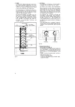
fig.17


