background image

E-4

* Power supply

65C-0i: 220-240V 10A

55C-0i: 220-240V 9A

45C-0i: 220-240V 8A

Note:

• This manual provides the illustrations of the

accessory parts and machine that may be

slightly different in shape from yours. In that

case, instead of the illustrations, use the ap-

pearance of your machine to follow the instal-

lation procedure.

This does not cause any significant change or

problem with the procedure.

• If none of the later steps instruct you to use the

parts including screw and cover that you re-

moved following the instructions described in

this manual, discard them.

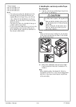
6. Installing the main body and the Paper
Feed Cabinet

(1) Take the main body and the Paper Feed Cabi-

net out from its packaging.

 CAUTION

Main body mass: approx. 100 kg (220-7/16

lb)

• Make available collective manpower of

an appropriate size for transporting the

main body.

• When holding the transportation han-

dles, be careful not to catch your fin-

gers in the machine.

Note:

Remove the main body, holding it by the handles

on the right and left sides as shown in the illustra-

tion and keeping it level.

(2) Refer to the installation manual for the Paper

Feed Cabinet and follow the “Installation Pro-

cedures.”

Note:

When installing either the Heater HT-509, the

Transformer kit TK-101, or the Power Supply BOX

MK-734 on the Paper Feed Cabinet, install them

at the same time.

Installation  Manual

Y119820-3

Содержание d-ColorMF659

Страница 1: ...Multifunction Digital Copier d ColorMF659 MF559 MF459 INSTALLATION MANUAL Code Y119820 3...

Страница 2: ...PUBLICATION ISSUED BY Olivetti S p A Gruppo Telecom Italia Strada Monte Navale 2 C 10015 Ivrea TO ITALY Copyright 2020 Olivetti All rights reserved...

Страница 3: ...iated options as a system follow the order shown on the upper CAUTION Main body mass approx 100 kg 220 7 16 lb Lifting the main body in an awkward position or transporting it in a poorly bal anced pos...

Страница 4: ...or unplug the power cord with wet or dirty hands otherwise you may get an elec tric shock 5 Avoid a hot and humid environment or a place exposed to direct sunlight 6 Avoid a dusty location or a place...

Страница 5: ...hand It is neces sary for mounting the Large Capacity Unit LU 302 WARNING Keep this bag away from babies and chil dren Do not use in cribs beds carriages or playpens The thin film may cling to nose an...

Страница 6: ...ng the main body and the Paper Feed Cabinet 1 Take the main body and the Paper Feed Cabi net out from its packaging CAUTION Main body mass approx 100 kg 220 7 16 lb Make available collective manpower...

Страница 7: ...protective sheet and locking materials Note After removing the locking materials make sure that the transfer roller assembly is se cured in place In the case of NG press the transfer roller assembly...

Страница 8: ...tructions on setting paper in each tray and configuring the paper types 6 Slide out the tray 2 and remove the tray locking materials 7 Remove the protective tapes from the inside of the tray 2 and rem...

Страница 9: ...e DF cable with the removed cable clamp as shown in the illustration One re moved screw 13 Open the lower front door 14 Remove the protective tape on the lower front door 15 Remove the four locking ma...

Страница 10: ...e lower front door 8 Installing the toner cartridge Note Since cartridge is not supplied with the machine purchase toner cartridge separately 1 Shake the toner cartridge up and down and left to right...

Страница 11: ...ation Pro cedures 10 Mounting the accessory parts 1 Remove the protective cover from the supplied stylus pen Note Discard the removed protective cover 2 Insert the stylus pen into the holder at the ri...

Страница 12: ...ce Mode screen For details of how to display the Service Mode screen see the service manual 2 Display the Date Time Setting Time Zone Setting screen To display the Date Time Setting Time Zone Setting...

Страница 13: ...Check For detailed information see the service manual 5 Touch OK 17 Configuring other options 1 If any of the following options are installed re fer to the Configuration procedures of the in stallati...

Страница 14: ...Route the network cable through the harness guide and pass it through the notch Note Leave an appropriate amount of slack in the por tion of the cable between the plug and the har ness guide in a mann...

Страница 15: ...ear right cover using nippers c Route the network cable through the harness guide and three wire saddles Note Leave an appropriate amount of slack in the por tion of the cable between the plug and the...

Страница 16: ...uch OK on the pop up window 8 Touch twice to return to the HOME screen then touch Maintenance 9 Touch PING TX Address to make the opera tion check of TCP IP 10 Touch the icon on the upper right of the...

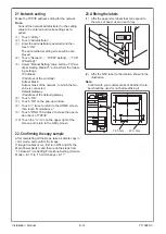
Страница 17: ...osition the rear side of the main body make sure that the stored contents such as a manual do not block the exhaust port of the duct cover If the optional Image Controller IC 420 is in stalled the hol...

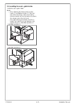
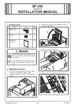
Страница 18: ...The thin film may cling to nose and mouth and prevent breathing This bag is not a toy 2 Installation procedures 1 Turn OFF the main power switch and unplug the power cord from the power outlet 2 Unloc...

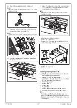
Страница 19: ...ith the roller Connector Rib 10 Reinstall the stamp unit cover 11 Close the original tray 12 Pinch the slot portion at the underside of the lock lever and pull it out Slot 13 Close the top door 3 Conf...

Страница 20: ...changes to the product described in this manual at any moment and without giving prior warning No part of this document may be copied reproduced or transmitted in any form or by any means electronic o...

Отзывы: