background image

36

Assembly

Before you can use  3D Ground Navigator  for a field measurement you should do some preparations.
Please pay attention to the following steps!

6.1 Charging the control unit

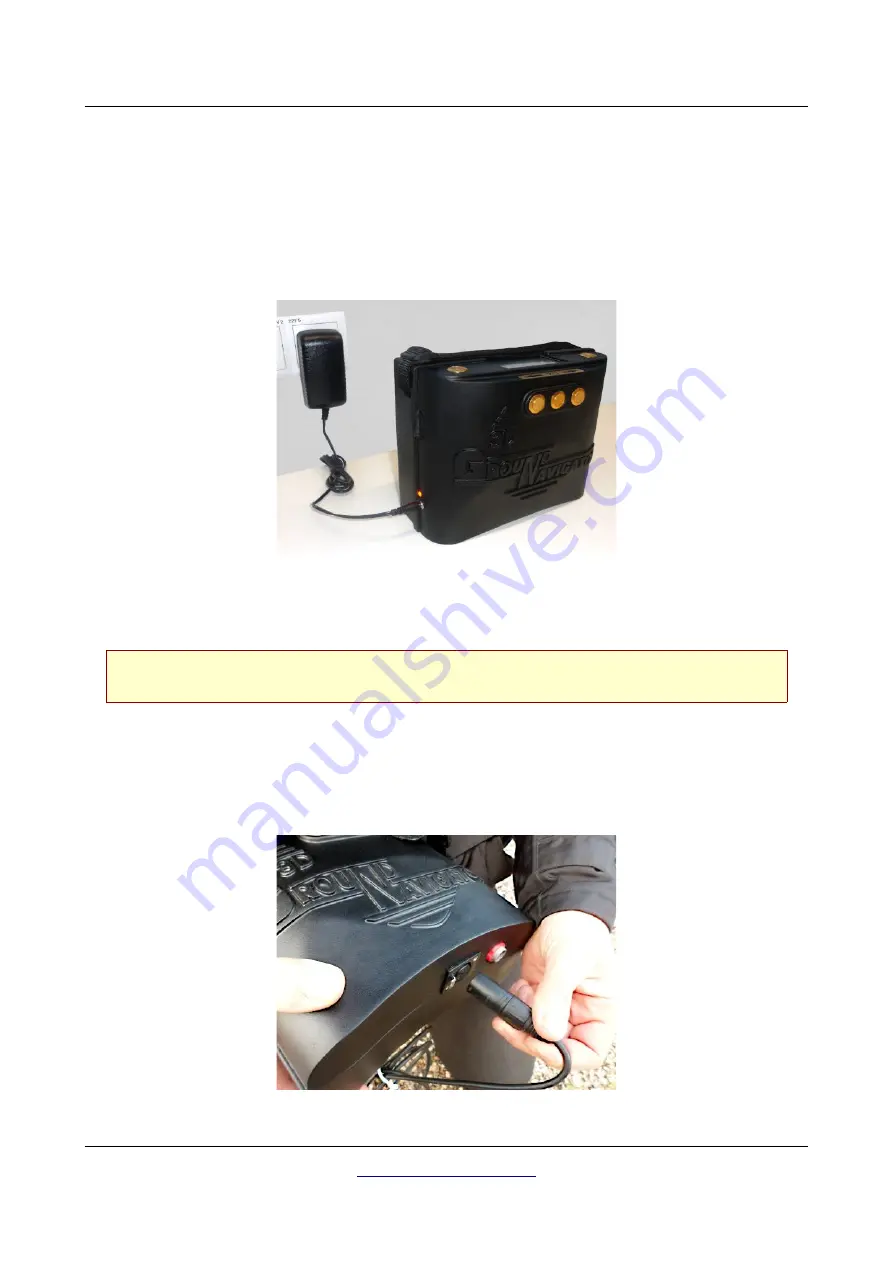
Switch off the device, connect the original charger with the charge socket of the detector and plug it in

into a power socket as shown in figure 6.1.

Now the Charge-LED will shine orange until the battery has been charged completely. After the battery

is fully charged, the Charge-LED turns off.

Only use original OKM chargers for recharging the internal battery!

Otherwise the battery may be damaged or explode.

6.2 Preparing the Control Unit

The Super Sensor is used to measure the underground values and should be connected to the socket on
the bottom of the unit. Avoid hard impact or other damages. Plug in the connector of the Super Sensor

until it locks into place (press the small release lock to detach the probe from the socket).

OKM GmbH

www.okmmetaldetectors.com

Figure 6.1: Charging the internal battery of the control unit

Figure 6.2: Connecting the Super Sensor

Содержание Future Series

Страница 1: ...FS Future Series 3D Ground Navigator Version 2 User s Manual ...

Страница 2: ...warranty In no circumstances OKM takes responsibility for lost profits usage or data losts interruption of business activities or all kind of other indirectly damages which developed because of errors in this documentation This instruction manual and all other stored media which are delivered with this package should only be used for this product Program copies are allowed only for security and sa...

Страница 3: ... software 20 4 1 1 Install software and driver 20 4 1 2 Configurate bluetooth dongle 22 4 1 3 Setup connection 25 4 2 Uninstall bluetooth software 25 5 Control elements 27 5 1 Breakdown of the Ground Navigator 28 5 2 Control unit 29 5 2 1 Top Front View 29 5 2 2 Bottom View 30 5 2 3 Touchscreen 31 5 2 4 Charging the internal battery 32 5 3 Super Sensor with LED orbit 32 5 4 Bluetooth Headphones 33...

Страница 4: ...tings 54 7 5 1 Headphones 54 7 5 2 Information 54 7 5 3 Bluetooth 55 7 5 4 Factory Reset 55 7 5 5 Back 56 8 Field procedure 57 8 1 General scanning procedure 58 8 1 1 Scan Mode 58 8 1 2 Regulation of the number of impulses per scanning path 59 8 2 Special advices for field procedure 61 8 2 1 Orientation of probe 62 8 2 2 Parallel or Zig Zag 62 8 2 3 Manual or automatic impulse mode 63 8 2 4 Tips f...

Страница 5: ...luetooth headphones with accessories 33 Figure 6 1 Charging the internal battery of the control unit 36 Figure 6 2 Connecting the Super Sensor 36 Figure 6 3 Connecting the Power Pack optional 37 Figure 6 4 Pocket the optional Power Pack optional 37 Figure 6 5 Power on your control unit and get ready to scan 38 Figure 7 1 Splash screen during boot up 40 Figure 7 2 Display representation in operatin...

Страница 6: ...an area 59 Figure 8 3 Effects of changing the number of impulses and their distance 60 Figure 8 4 Comparison of low and high number of impulses 60 Figure 8 5 Different walking speeds during scanning 61 OKM GmbH www okmmetaldetectors com ...

Страница 7: ...1 Introduction CHAPTER 1 Introduction ...

Страница 8: ...ourse of your research that you will be successful and have a find The recognition of hidden and buried objects depends on a huge number of factors As you well may know there are different soil types all over the world with different levels of natural attenuation Variable soil properties can and will hamper and alter ultimate scan measurements Areas where there is an extreme amount of ground water...

Страница 9: ...re no end user serviceable parts on the inside of the unit 1 2 2 Possible Health Hazards If used properly this device normally does not pose any health hazards According to current scientific knowledge the high frequency signals are not harmful to the human body on account of their low power 1 2 3 Surrounding Area When moving this unit from a cold place to a warmer place watch out for condensation...

Страница 10: ...ll batteries and accumulators are fully charged Also allow the batteries to completely discharge before recharging them regardless if you are working with the external battery or with internal accumulators This way your batteries will have a long and durable life To charge the external and internal batteries use only the approved chargers which are part of our scope of delivery 1 4 Danger of Explo...

Страница 11: ...nents have been rusting away in the course of time and the slightest movement may cause parts of them to break and be triggered Even seemingly harmless objects such as cartridges or large ammunition are anything but that Explosives may have become crystalline over time that is sugar like crystals have formed Moving such an object may cause those crystals to produce friction leading to an explosion...

Страница 12: ......

Страница 13: ...2 Technical specifications CHAPTER 2 Technical specifications ...

Страница 14: ... Pack 12 5 VDC 0 9 A max 24 VDC 0 5 A Processor Main CPU Cortex M3 32 MHz Processor Slave CPU Cortex M0 24 MHz Display 3 5 Resistive touch 480 x 320 Pixel Display CPU Cortex M3 32 MHz 128 KB RAM Data memory 4 GB Sample rate 1024 values second Measurement resolution 16 bit Operating temperature 10 60 C Storage temperature 20 70 C Audio Internal speaker Bluetooth Air humidity 5 75 Waterproof No 2 2 ...

Страница 15: ...choose of a suitable computer to analyze your measured scan data CD ROM drive internal or external min 4x Interface data transmission USB Free disk space min 50 MB Working memory RAM min 256 MB Graphic card min 128 MB OpenGL compatible Operating system Windows 7 Windows 8 Windows 10 OKM GmbH www okmmetaldetectors com ...

Страница 16: ......

Страница 17: ...3 Scope of delivery CHAPTER 3 Scope of delivery ...

Страница 18: ...some optional accessories which are not included in the basic equipment Description Quantity Control unit with carrying strap 1 Bluetooth headphones 1 Super Sensor with LED orbit 1 Software Visualizer 3D 1 Charger for control unit 1 Bluetooth dongle 1 Carrying case 1 User s manual 1 Carrying tube for Super Sensor 1 Power Pack optional Table 1 Scope of delivery OKM GmbH www okmmetaldetectors com ...

Страница 19: ...th CHAPTER 4 Data transfer via bluetooth In this section you will learn how to install the bluetooth software on your computer This software is necessary to transfer all measured data from your 3D Ground Navigator to the computer ...

Страница 20: ...ware is situated on the software CD which is included in the scope of delivery Place the CD inside the CD Rom drive of your computer and wait until a window like shown in figure 4 1 appears Click on the entry Bluetooth to start the installation of the bluetooth software and follow the instructions on the screen of your computer like it is explained in the following steps OKM GmbH www okmmetaldetec...

Страница 21: ...tallation of bluetooth software step 2 Figure 4 5 Installation of bluetooth software step 4 Step 2 Click on Next Step 4 Click on Next Figure 4 4 Installation of bluetooth software step 3 Step 3 Mark the entry I accept the terms in the license agreement and after that click on Next ...

Страница 22: ...find the bluetooth icon grey white on the down right side of the task bar If you do not find this symbol there you should start the bluetooth software manually In this case just click on the bluetooth symbol which has been created on your desktop during the installation OKM GmbH www okmmetaldetectors com Figure 4 6 Installation of bluetooth software step 5 Step 5 Click on Install Figure 4 7 Instal...

Страница 23: ...n continue with step 9 OKM GmbH www okmmetaldetectors com Figure 4 8 Installation of bluetooth software step 7 Step 7 Double click on the new created bluetooth symbol on your desktop to open a window like here on the right side Figure 4 9 Installation of bluetooth software step 8 Step 8 Plug in the bluetooth dongle in a free USB connection of your computer When the dialog from the left figure appe...

Страница 24: ... 9 Step 9 Click in the menu on View Service window to see the installed services Figure 4 11 Installation of bluetooth software step 10 Step 10 Behind the entry Serial Port A you can find the assigned COM port which you should select during the data transfer in the software Visualizer 3D In our example here it is COM6 ...

Страница 25: ... the bluetooth dongle delivered with the device 4 2 Uninstall bluetooth software In this section it is explained how to delete the bluetooth software from your computer Therefor click on the entry Start All Programs IVT BlueSoleil Uninstall BlueSoleil and follow the instruction on the screen of your computer After uninstalling your bluetooth drivers you should reboot your computer OKM GmbH www okm...

Страница 26: ......

Страница 27: ... elements CHAPTER 5 Control elements In this section you will learn more about the fundamental use of all control elements for this measuring instrument All connections inputs and outputs are explained in detail ...

Страница 28: ...ures the environment and transfers all data to the control unit for further processing The Super Sensor comes with a LED orbit to visualize detected objects If the control unit is connected with Wireless Headphones it will turn off the internal speaker For much longer operating times an optional Power Pack can be utilized with the detector OKM GmbH www okmmetaldetectors com Figure 5 1 3D Ground Na...

Страница 29: ... appropriate section within this manual By using the arrow buttons and you can switch between the operating modes in the main menu and select the options in submenus With these arrow buttons you can finish the measurement of an operating mode and get back into the main menu Power on off button With the power on off button you can switch on or off the device When the device is powered off and you p...

Страница 30: ...ge LED is shining orange See section 5 2 4 Charging the internal battery on page 32 for more details about charging the control unit Socket for power pack Additional to the internal battery it is possible to connect OKM s optional Power Pack By using this Power Pack you can extend your operating time by another 48 hours Socket for probe At this socket you should connect the Super Sensor Without pr...

Страница 31: ...ing the button Next When this area is touched with your finger the next possible option is shown If you reach the last of all available options it will automatically jump back to the first option The same effect can be achieved by using the button Confirm OK When this area is touched with your finger the current option will be confirmed The same effect can be achieved by using the OK button Back C...

Страница 32: ...fter the battery is fully charged the Charge LED turns off Only use original OKM chargers for recharging the internal battery Otherwise the battery may be damaged or explode 5 3 Super Sensor with LED orbit The Super Sensor is equipped with a light sphere called LED orbit that can indicate the measured values visually during the scanning process Start button This button has exactly the same functio...

Страница 33: ...er on your Bluetooth headphones and push the pairing button The 3D Ground Navigator tries connecting for 60 seconds If the Bluetooth connection between headphones and device can be established successfully the speaker icon switches to a headphones icon Otherwise you should try again See also section 7 5 1 Headphones on page 54 for more detailed information regarding connecting the Bluetooth headph...

Страница 34: ......

Страница 35: ...6 Assembly CHAPTER 6 Assembly In this section is explained how to assemble the device and how to prepare a measurement ...

Страница 36: ... battery is fully charged the Charge LED turns off Only use original OKM chargers for recharging the internal battery Otherwise the battery may be damaged or explode 6 2 Preparing the Control Unit The Super Sensor is used to measure the underground values and should be connected to the socket on the bottom of the unit Avoid hard impact or other damages Plug in the connector of the Super Sensor unt...

Страница 37: ...on the connector it will be detached from the socket Now switch on the Power Pack The LED indicator will shine green Please refer to the user s manual of the Power Pack for further information concerning its use After connecting and switching on the Power Pack you can simply put it in any of your pockets OKM GmbH www okmmetaldetectors com Figure 6 4 Pocket the optional Power Pack optional Figure 6...

Страница 38: ...bly Now you should power on the device with the power on off button and you are ready to perform your measurements OKM GmbH www okmmetaldetectors com Figure 6 5 Power on your control unit and get ready to scan ...

Страница 39: ...7 Operating modes CHAPTER 7 Operating modes In this section you will learn more about operating the device Every operating mode will be explained in a proper subsection ...

Страница 40: ...data to Visualizer 3D software to pinpoint potential targets Magnetometer Process an acoustical magnetic field measurement to detect ferrous metals Transfer to PC Transfer stored measurements to Visualizer 3D software Settings Adjust general settings like Bluetooth address headphones connection etc The choice of the operating mode depends on the planned mission Normally you should use several oper...

Страница 41: ...plain these parameters in more detail Step 1 Power on the device and select the operating mode Ground Scan from the main menu If there is no probe connected the button is disabled Step 2 If the Super Sensor is connected please confirm the operating mode Ground Scan by pushing the OK button Step 3 Impulse Mode The impulse mode sets the way of how the single impulses measure values will be released ...

Страница 42: ...been sent out If you select Automatic you are not able to do a direct transfer to a computer You can only store the measured values in the internal memory of the device because the exact length of field is not yet selected 10 20 200 Each scanning path consists of the selected number of measure points At the end of each scanning path the device stops by itself as soon as the number of measure point...

Страница 43: ... get ready and start your first scan line by pushing the start button Read section 7 1 2 Conducting the measurement on page 44 to learn more about conducting a complete ground scan If you are going to finalize this operating mode simply push one of the arrow buttons or 7 1 1 2 Transferring to computer If you selected Computer as transfer mode you need to establish a wireless data connection with O...

Страница 44: ...ush one of the arrow buttons or Step 10 After canceling the Ground Scan screen the device also exits the wireless data connection before returning back to the main menu 7 1 2 Conducting the measurement After all parameters has been adjusted the device is ready to start the first scanning path Beginning from this moment the display will indicate the current number of scanning paths and the current ...

Страница 45: ...y one with the start button The impulses will not be sent out automatically Now you should do a little step forward and press the start button again to measure the second measure point The device stops and you should again walk a little step forward and press the start button once more Now continue in this way until you have reached the end of the first scanning path If you already have defined th...

Страница 46: ...the measuring area you should research in detail with the Super Sensor 7 2 1 Preparing a Pin Pointer scan In this operating mode all measured data will be sent directly to a computer Therefor a wireless data connection to the Visualizer 3D software must be established first Step 1 Power on the device and select operating mode Pin Pointer from the main menu If there is no Super Sensor connected the...

Страница 47: ...w push the start button of the detector to start recording Step 6 The display now shows the active Pin Pointer screen You can repeat the ground balance at any time by pushing the start button If you are going to cancel this operating mode simply push one of the arrow buttons or Step 7 After canceling the Pin Pointer screen the device also exits the wireless data connection before returning back to...

Страница 48: ...plete object which means you should measure beyond the edges of the object Repeat this measurement a few times to get a clear signature of the object During this procedure the Super Sensor should point vertical towards the ground It should not be turned or pivoted You may push the start button from time to time to repeat ground balancing the metal detector To quit the operating mode Pin Pointer an...

Страница 49: ...ll change continuously Take care to move the Super Sensor slowly and equal above the ground and above a detected object to get a clear signature The figure 7 7 represents a signature of a non ferrous target You can recognize that there is only a positive amplitude red Additionally to the main amplitude there is another small peak which is typically for precious metals Also here the order of amplit...

Страница 50: ...se note that it can also react on metallic trash or contamination laying on the surface or near to the surface 7 3 1 Preparing a Magnetometer scan There is not much to prepare to conduct a scan in Magnetometer mode Simply follow these steps Step 1 Power on the device and select the operating mode Magnetometer from the main menu If there is no probe connected the button is disabled Step 2 If a prop...

Страница 51: ...nd balance Make sure you hold the Super Sensor straight downwards to the ground as you would do during the scanning process and run the ground balance by pushing the start button With that the sound output should be silent Now you can move slowly forward backwards and sidewards but should avoid turning the probe The probe should always point vertical to the ground and should not be turned around i...

Страница 52: ...d object was situated you can simply use the Magnetometer mode to relocate fast and efficient the target position After using this operating mode for a while you should process a new ground balance by pushing the start button To finish the operating mode Magnetometer and return back into the main menu you simply push one of the arrow buttons or 7 4 Transfer to PC By using the operating mode Transf...

Страница 53: ... device is connecting with the PC and tries to establish a valid Bluetooth connection Step 5 Now the device transfers all data from internal memory to your computer Simultaneously you should see incoming measure values in Visualizer 3D Step 6 After all data has been transferred the Bluetooth connection gets disconnected and you will get back to the main menu OKM GmbH www okmmetaldetectors com ...

Страница 54: ...phones and push the headphones pairing button The actual pairing process can be different from headphone to headphone The program will wait 60 seconds to connect to the headphones If it is successful the speaker icon will change to a headphones icon 7 5 2 Information This option displays information concerning the device s serial number and firmware version Those information may be useful if you a...

Страница 55: ...OK button to confirm the change You will return back to the settings menu 7 5 4 Factory Reset This option will reset all configurations back to factory defaults For safeness purposes an additional question pops up to avoid accidental factory resets Running the factory reset will clear all personal configuration changes If you individually changed the Bluetooth address also this setting will be cle...

Страница 56: ...o the main menu especially when using the hardware buttons only If you are using the touchscreen capabilities you simply touch the icon instead This icon will always indicate to go back to the previous screen OKM GmbH www okmmetaldetectors com Figure 7 15 Back screen ...

Страница 57: ...ield procedure CHAPTER 8 Field procedure This chapter gives practical instructions about the general procedure of scanning an area The different scanning methods and procedures will be explained in detail ...

Страница 58: ... point for your measurement by yourself The scanning paths may be referred as Zig Zag or Parallel traverses Also the number of impulses measure points which are recorded during one scanning path can be adjusted individually depending on the size of your scan area length of scanning path 8 1 1 Scan Mode There are two general techniques to surveying an area with the 3D Ground Navigator Zig Zag The s...

Страница 59: ...ure area If you mostly look for smaller targets than you should also select a smaller distance between the lines A standard rule is The smaller the distance between the paths the more accurate your scans will be When you are conducting your first scans the lines should not be to close together to locate possible targets 8 1 2 Regulation of the number of impulses per scanning path It is possible to...

Страница 60: ...tion will be If you are looking for small objects you have to select a smaller distance for big objects you can increase the distance between the impulses Figure 8 3 shows the effects of the distance and the number of impulses per scanning path for some objects Figure 8 4 shows the difference between very few impulses left side and much more impulses right side on the same length of scanning path ...

Страница 61: ... advices for field procedure There are some aspects which you should take note of when conducting scans In principle a scan is only as good as the path that was taken Making errors while scanning will show up in the final graphical representation also as an error This will cause frustration and lost time Before you start with a measurement in the field you should think of what you are looking for ...

Страница 62: ...ys the same distance to the ground Generally we recommend a height of about 5 15 cm from the surface of the ground if possible In the event that you are going to go over stones wood or high grass that is higher start your scan with the sensor higher right from the beginning In circumstances like these then perhaps you will need to start the scan with the probe at a height of 2 feet 50 cm and keep ...

Страница 63: ...ture of the soil and creates some kind of noise Usually the buried object has a weaker signature than the unnatural noise and therefor is not detectable So taken scan images will not show the buried item but visualize the noisy area in blue colors After the item has been seasoned meaning it has been in the ground for a complete cycle of seasons usually a year the noise gets reduced and the signatu...

Страница 64: ...unt in There are two factors of sand that need to be noted Sand where the ground water is very shallow meaning that the ground water is usually just a couple of meters from the surface or desert sand where it is very arid In desert sand the targets can be situated 3x deeper than indicated Farmland is another area to take note of In modern farms so many nutrients and fertilizers are introduced crea...

Отзывы: