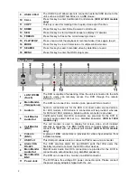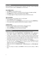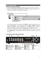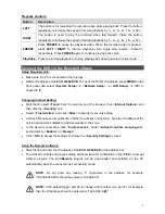
3
Pin Definition of Alarm I/O & RS-485, and Audio In
Alarm I/O & RS-485:
4CH models:
Pin Definition
Pin Definition
Pin Definition
Pin Definition
1
Alarm Out Open
5
Alarm In 1
9
Alarm Out Close
13
GND
2
Alarm Out COM
6
Alarm In 2
10
GND
14
GND
3
RS485 D+
7
Alarm In 3
11
GND
15
GND
4
RS485 D
−
8
Alarm In 4
12
GND
8CH & 16CH models:
Pin Definition
Pin Definition
Pin Definition
1
Alarm Out Open
10
Alarm In 5
19
Alarm In 10 (16CH)
2
Alarm Out COM
11
Alarm In 6
20
Alarm In 11 (16CH)
3
RS485 D+
12
Alarm In 7
21
Alarm In 12 (16CH)
4
RS485 D
−
13
Alarm In 8
22
Alarm In 13 (16CH)
5
Reserved
14
Alarm Out Close
23
Alarm In 14 (16CH)
6
Alarm In 1
15
Reserved
24
Alarm In 15 (16CH)
7
Alarm In 2
16
Reserved
25
Alarm In 16 (16CH)
8
Alarm In 3
17
Reserved
9
Alarm In 4
18
Alarm In 9 (16CH)
Audio In:
Pin Definition
Pin Definition
Pin Definition
Pin Definition
1
Audio 1
8
Audio 15 (16CH)
15
Audio 4
22
GND
2
Audio 3
9
GND
16
Audio 6
23
GND
3
Audio 5
10
GND
17
Audio 8
24
GND
4
Audio 7
11
GND
18
Audio 10 (16CH)
25
Reserved
5
Audio 9 (16CH)
12
GND
19
Audio 12 (16CH)
6
Audio 11 (16CH)
13
Reserved
20
Audio 14 (16CH)
7
Audio 13 (16CH)
14
Audio 2
21
Audio 16 (16CH)
Power On the DVR
Please follow the proper power on procedures to avoid damaging the DVR.
•
Connect all necessary components, e.g. monitor and cameras, before power on the DVR.
•
Check the type of power source before connecting the power adaptor to the DVR. The
acceptable power input is between AC110V ~ AC240V.
Select Viewing Mode:
•
Press
MODE
repeatedly to select the wanted display mode. The available viewing modes are
full-screen, 2×2, 3×3, and 4×4 split-window.
•
Press
FREEZE
to pause the current viewing image.
•
Refer to the following for a brief description of some icons that will be shown on the monitor.
Icon Description
Position
Icon Description
Position
►
Playback Mode
Lower-left corner
Key Locked
Center-bottom
N Not Logged-in
Upper-right corner 1~8 User’s Authority Level Upper-right corner


