4 – 4
Item
No.
Specification
Drawing
Adjustment method
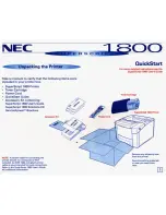
Gap between the con-
tact and the monitor
0.3mm or more
Touching
Adjust lever
Contact
Motor PCB
Verify the following.
Make sure that the
gap between the con-
tact and the motor
PCB is 0.3 mm or
more.
At the time of printing
test, make sure that
the contact touches
the motor PCB and it
enters reduced speed
mode when the adjust
lever is set to range 2
and 4.
0.3mm or
more
Содержание MICROLINE 320
Страница 7: ...1 2 1 2 Options 1 Cut sheet feeder unit CSF Attachment assy 2 Pull tractor assy Single bin CSF...
Страница 8: ...1 3 3 Bottom push tractor unit 5 Serial I F RS 232C 4 Roll paper stand Narrow only...
Страница 36: ...2 28 Figure 2 6 Ribbon cartridge Drive gear Ink reservoir...
Страница 47: ...2 39 Figure 2 14 Change lever Release cam Platen Front release gear arm TOP BOTTOM REAR Pressure rollers...
Страница 49: ...2 41 Paper end sensor Sensor lever Shaded portion A B Paper end lever Bottom paper end lever Figure 2 15 C...
Страница 51: ...2 43 Platen Figure 2 16 Ribbon protector Printhead Carriage frame assembly...
Страница 90: ...5 2 Carriage shaft...
Страница 98: ...5 10 9 Carriage Assy NK2 10 SUS Bearing part of the guide roller EM 30L B...
Страница 119: ...6 21 Replace RS232C board Remedied No Yes End Replace driver board...
Страница 121: ...B 1 B SPARE PARTS LIST...
Страница 122: ...B 2 Figure 11 1 Upper Cover Assy 1 2 3 4...
Страница 124: ...B 4 Figure 11 2 Printer General Assy 6 9 8 2 7 4 5 3 10 1...
Страница 129: ...B 9 Figure 11 4 Carriage Assy 12 9 8 6 14 11 10 1 13 7 5 4 3...
Страница 131: ...B 11 Figure 11 5 Option Spare Parts 1 2 3 4 5 6 7 Pull Tractor Bottom Tractor I F Board...
Страница 145: ...Microline 320 321 Turbo Service Manual Part Number 59273701 Printed in the USA...