3 – 25
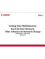
3.3.21 Rear Pressure Assy
(1)
Remove the upper cover (see 3.3.4).
(2)
Remove the change lever and gears (see 3.3.17).
(3)
Remove the paper pan (see 3.3.19).
(4)
Remove the rear pressure roller
1
.
(5)
Rotate the release shaft
2
and move it to the left to detach the release shaft
2
.
Match the main frame rib A with the protrusion B of the release shaft.
(6)
Remove rear pressure SP assy
3
.
(7)
To install, follow the removal steps in reverse order.
Note: (1) When installing the release shaft
2
, pay attention to the gear engagement of
release shaft
2
, change arm lever
6
, and change gear shaft
7
.
(2) On the ML321 Turbo there are 5 rear pressure spring assemblies. Use the
two pieces which have larger spring diameter on the right side. Use the three
remaining pieces on the left side.
(3) Make sure that the release shaft
2
will be on top of the support spring
4
.
(4) To assemble the release shaft
2
, make sure that the protrusion of the switch
lever
5
is in the U groove of the release shaft
2
.
7
6
2
4
1
4
2
5
3
1
3
2
A
B
Содержание MICROLINE 320
Страница 7: ...1 2 1 2 Options 1 Cut sheet feeder unit CSF Attachment assy 2 Pull tractor assy Single bin CSF...
Страница 8: ...1 3 3 Bottom push tractor unit 5 Serial I F RS 232C 4 Roll paper stand Narrow only...
Страница 36: ...2 28 Figure 2 6 Ribbon cartridge Drive gear Ink reservoir...
Страница 47: ...2 39 Figure 2 14 Change lever Release cam Platen Front release gear arm TOP BOTTOM REAR Pressure rollers...
Страница 49: ...2 41 Paper end sensor Sensor lever Shaded portion A B Paper end lever Bottom paper end lever Figure 2 15 C...
Страница 51: ...2 43 Platen Figure 2 16 Ribbon protector Printhead Carriage frame assembly...
Страница 90: ...5 2 Carriage shaft...
Страница 98: ...5 10 9 Carriage Assy NK2 10 SUS Bearing part of the guide roller EM 30L B...
Страница 119: ...6 21 Replace RS232C board Remedied No Yes End Replace driver board...
Страница 121: ...B 1 B SPARE PARTS LIST...
Страница 122: ...B 2 Figure 11 1 Upper Cover Assy 1 2 3 4...
Страница 124: ...B 4 Figure 11 2 Printer General Assy 6 9 8 2 7 4 5 3 10 1...
Страница 129: ...B 9 Figure 11 4 Carriage Assy 12 9 8 6 14 11 10 1 13 7 5 4 3...
Страница 131: ...B 11 Figure 11 5 Option Spare Parts 1 2 3 4 5 6 7 Pull Tractor Bottom Tractor I F Board...
Страница 145: ...Microline 320 321 Turbo Service Manual Part Number 59273701 Printed in the USA...