


92
Item No.
9
10
Items
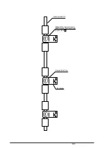
Installing print head
Alignment of horizontal
printing
Standard Value Illustration Adjustment Method
1
In installing the printhead, accurately
bump it to the impinging plate on the
carriage frame.
Notes:
The print head should be installed/
removed at 1-range position.(prevent
protector deformation)
2
How to tighten screws in installing
the printhead.
a.Lightly tighten the right and left screw
while pushing the print head against
the carriage.
b.In tightening the screws first, (note)
make sure to tighten the left screw af-
ter tightening the right screw while
pushing the head against the carriage.
Notes 1:
To prevent the float of head when tight-
ening the screws.
Notes 2:
Tightening the screws while pressing
the head in the direction of " ".
3
Adjust the backlash of screws so
that the print head can meet the
center of the protector.
1
Set a continuous paper (1P, 15 inch
width, 55kg sheet) onto the printable
position.
2
Press
5
switch to go to the menu
mode. Press
2
to display "Set-Up".
Next, press
3
to display
"Registration1". (The printer starts
Registration1 printing.)
Open the access cover to confirm that
the printing is in progress and close it,
and then execute the correction after
pressing the ON-LINE switch.
Print head
Carriage frame
Impinging plate
Print head
Left screw
Right screw
Mounting screw
Print head
Install the print head so that the
center of the print head meet that
of protector.
Protector frame
Содержание PACEMARK 4410
Страница 2: ...1 PACEMARK 4410 PRINTER Service Manual...
Страница 53: ...52 Figure 3 1 3 2 Parts Layout...
Страница 96: ...95...
Страница 104: ...103 Apply a small amount of Albania grease on the stud sliding surface GEP B both right and left...
Страница 130: ...129 1 1 The cable to POA Board CN1 connected properly Yes No Connect the cable properly Replace POA Board or PMA Board...
Страница 152: ...151 No Yes End Replace PHA Board Recovered No Yes End Replace PMA Board...
Страница 178: ...118 Carriage Assy Unit 40501901 20 9 19 19 24 24 11 9 8 24 14 13 5 4 3 26 2 1 22 7 10 18 17 16 25 23 12 15 6...
Страница 180: ...120 Knob Assy 40782001 8 4 6 3 5 10 7 1 2 9...
Страница 182: ...122 Ribbon Assy Feed 40506101 1 15 8 7 8 14 6 5 10 13 3 4 13 2 6 7 14 9 11 11 1...
Страница 184: ...124 Sprocket Assy L 40507601 3 2 5 6 1 19 19 7 4 21 10 8 9 20 18...
Страница 186: ...126 Sprocket Assy R 40508101 3 7 11 11 1 6 5 2 13 4...
Страница 188: ...128 Sheet Feeder Assy L Rear 40508701 9 10 4 16 2 12 5 6 7 13 11 3 8 1 14 10 15 16 Pin Protrucsion...
Страница 190: ...130 Sheet Feeder Assy R Rear 40509101 8 11 1 9 4 13 13 10 6 5 2 9 12 7 3 Pin Protrusion...
Страница 192: ...132 Bail Assy 40499601 22 22 22 22 8 11 21 23 16 1 21 3 16 17 18 13 14 23 7 10 19 5 21 12 9 15 6...
Страница 194: ...134 Lower Cover Assy 40677101 14 12 9 6 18 17 16 11 3 3 4 15 4 15 4 10 10 1 3 3 7 5 5 16 8 16 15 4 15 5 14 14...
Страница 196: ...136 Front Cover Assy 40677201 ODA 40677202 OEL 10 6 9 9 9 2 4 4 1 3 7 7 5 9 10 10 6 6...
Страница 198: ...138 Rear Cover Assy 40678301 11 6 5 9 10 10 8 10 10 10 9 4 1 10 3 2 7 13...
Страница 200: ...40496501TH Draft Version 140 Access Cover 40520201 1 6 4 3 8 10 10 10 9 7 8 3 4 6 5 2 8 13 13 13 11 12...
Страница 202: ...142 Frame Assy OpePane 40755801 3 2 4 6 8 9 9 1 5...
Страница 204: ...144 PMA PDA PCB Assy 40752201 4075202 4 or 6 5 or 7 1 or 2 3 8 9 11...
Страница 208: ...148 5 Circuit board PRA Connection CN1 CN2 CN9 CN6 CN4 CN2 CN13 CN8 CN10 CN3 F1 6 Circuit board PGA Sensor SN1 CN1...