


11
2. THEORY OF OPERATION
2.1 Electrical Operation
The electrical operation of the printer circuit is described in this section.
2.1.1 Summary
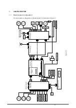
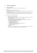
Fig. 2-1 shows the block diagram of the printer.
The control board is made up of the microprocessors, peripheral circuits, drive circuits, sensors and
interface connectors.
The power to the control board is supplied by the power board through the connector cord.
The power to other electrical parts is also distributed through the connectors within the control board.
2.1.2 Microprocessor and the peripheral circuit
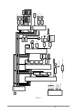
(1) Microprocessor (IC24: 80C186-16)
This processor is a CMOS single-chip computer with integrated peripheral device functions
and a 16 bit MPU core.
The processor has a 20 bit address bus and a 16 bit data bus.
It is capable of accessing up to 4M bit program memory and 4M bit of data memory.
The following characteristics are also provided:
• High-Speed DMA Channel x 2
• Programmable Interrupt Controller
• Programmable 16-bit Timer x 3
• Programmable Memory and Peripheral Chip-Select Logic
• Programmable Wait State Generator
• Local Bus Controller
And others.
The function of this microprocessor is to provide a central mechanism for the entire printer
by executing the control program through the LSI and driver circuits.
Содержание PACEMARK 4410
Страница 2: ...1 PACEMARK 4410 PRINTER Service Manual...
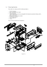
Страница 53: ...52 Figure 3 1 3 2 Parts Layout...
Страница 96: ...95...
Страница 104: ...103 Apply a small amount of Albania grease on the stud sliding surface GEP B both right and left...
Страница 130: ...129 1 1 The cable to POA Board CN1 connected properly Yes No Connect the cable properly Replace POA Board or PMA Board...
Страница 152: ...151 No Yes End Replace PHA Board Recovered No Yes End Replace PMA Board...
Страница 178: ...118 Carriage Assy Unit 40501901 20 9 19 19 24 24 11 9 8 24 14 13 5 4 3 26 2 1 22 7 10 18 17 16 25 23 12 15 6...
Страница 180: ...120 Knob Assy 40782001 8 4 6 3 5 10 7 1 2 9...
Страница 182: ...122 Ribbon Assy Feed 40506101 1 15 8 7 8 14 6 5 10 13 3 4 13 2 6 7 14 9 11 11 1...
Страница 184: ...124 Sprocket Assy L 40507601 3 2 5 6 1 19 19 7 4 21 10 8 9 20 18...
Страница 186: ...126 Sprocket Assy R 40508101 3 7 11 11 1 6 5 2 13 4...
Страница 188: ...128 Sheet Feeder Assy L Rear 40508701 9 10 4 16 2 12 5 6 7 13 11 3 8 1 14 10 15 16 Pin Protrucsion...
Страница 190: ...130 Sheet Feeder Assy R Rear 40509101 8 11 1 9 4 13 13 10 6 5 2 9 12 7 3 Pin Protrusion...
Страница 192: ...132 Bail Assy 40499601 22 22 22 22 8 11 21 23 16 1 21 3 16 17 18 13 14 23 7 10 19 5 21 12 9 15 6...
Страница 194: ...134 Lower Cover Assy 40677101 14 12 9 6 18 17 16 11 3 3 4 15 4 15 4 10 10 1 3 3 7 5 5 16 8 16 15 4 15 5 14 14...
Страница 196: ...136 Front Cover Assy 40677201 ODA 40677202 OEL 10 6 9 9 9 2 4 4 1 3 7 7 5 9 10 10 6 6...
Страница 198: ...138 Rear Cover Assy 40678301 11 6 5 9 10 10 8 10 10 10 9 4 1 10 3 2 7 13...
Страница 200: ...40496501TH Draft Version 140 Access Cover 40520201 1 6 4 3 8 10 10 10 9 7 8 3 4 6 5 2 8 13 13 13 11 12...
Страница 202: ...142 Frame Assy OpePane 40755801 3 2 4 6 8 9 9 1 5...
Страница 204: ...144 PMA PDA PCB Assy 40752201 4075202 4 or 6 5 or 7 1 or 2 3 8 9 11...
Страница 208: ...148 5 Circuit board PRA Connection CN1 CN2 CN9 CN6 CN4 CN2 CN13 CN8 CN10 CN3 F1 6 Circuit board PGA Sensor SN1 CN1...