


31
2.1.14 Alarm circuits
(1) Driver circuit abnormality detection alarm.
This protective circuit prevents secondary troubles by stopping the power supply upon
detection of an abnormality in the print head, SP motor driver circuit or other motor driver
circuits.
This circuit monitors the driving time by means of the signals (DT1COM1, SPV, LF COM, AG-
MCOM, RBN-MCOM, TR-MCOM, BEIL-MCOM and RENCOM) connected to the overdrive
signals for each driver circuit. If any driver circuit driving time exceeds the specified time, the
POWOFF-P signal is output to switch off the power supply to stop all DC voltage outputs.
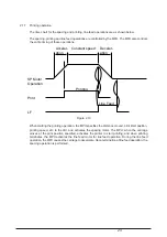
(2) Head high temperature alarm circuit
The thermistor built in the head monitors the head temperature for head coil protection.
If high duty printing continues for a long time, the head temperature rises. If it reaches a
certain level (approx. 148
°
C and 158
°
C), head high temperature alarm 1 is detected to start
one-way printing with a 40 ms interval after each line. When head temperature alarm 2 is
detected to start one-way and two-pass printing with a 1.2 sec. interval after each line for the
head temperature to fall. When the temperature falls to below the detection temperature,
normal printing operation restarts.
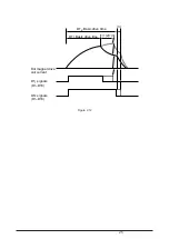
As the head temperature rises, the resistance of the thermistor decreases and the potential
of the input to the comparator in the head thermistor alarm circuit rises, when the potential
goes above the alarm 1 specific level, MPU goes into alarm 1 procedure, simultaneously MPU
continues to check if the potential goes above alarm 2 specific level. When going below alarm
2 level, MPU goes into alarm 2 procedure.
(3) Paper end detection circuit
Five sensors (front tractor paper end sensor, rear tractor paper end sensor, sheet jam sensor,
sheet top sensor and sheet width sensor) are provided for different paper set routes to monitor
paper end. When paper runs out, the corresponding sensor is turned off to input the
FTRPESW-P, RTRPESW-P, SHEETJAM-P, SHEETTOP-P, SHEETWITH-N signal to the
sub LSI (IC17), and is read by the MPU. The MPU stops the printing operation, informs the
host of the paper end and jam, and lights the alarm lamp.
(4) Cover open alarm circuit
When the front access cover is PUSH opened, the COVEROPN1SW-P signal is input to the
main LSI and the NHDC LSI from the cover open microswitch, and an invalid signal is input
to MPU. The MPU stops the printing operation as soon as possible, informs the host that
receiving is impossible, and lights the alarm lamp.
When the front access cover is opened and, the interlock switch cuts the SP motor drive
current and makes the SP motor stop.
(5) Fan alarm circuit
For each of the five fans, the FANALM-P signal is provided to detect fan rotation/stop. The
signal is at Low level when the fan rotates, while it becomes High when it stops. The MPU
monitors this signal level. When the High level is kept for one minute or longer, the MPU stops
the printing operation, informs the host of the fan alarm, and lights the alarm lamp.
Содержание PACEMARK 4410
Страница 2: ...1 PACEMARK 4410 PRINTER Service Manual...
Страница 53: ...52 Figure 3 1 3 2 Parts Layout...
Страница 96: ...95...
Страница 104: ...103 Apply a small amount of Albania grease on the stud sliding surface GEP B both right and left...
Страница 130: ...129 1 1 The cable to POA Board CN1 connected properly Yes No Connect the cable properly Replace POA Board or PMA Board...
Страница 152: ...151 No Yes End Replace PHA Board Recovered No Yes End Replace PMA Board...
Страница 178: ...118 Carriage Assy Unit 40501901 20 9 19 19 24 24 11 9 8 24 14 13 5 4 3 26 2 1 22 7 10 18 17 16 25 23 12 15 6...
Страница 180: ...120 Knob Assy 40782001 8 4 6 3 5 10 7 1 2 9...
Страница 182: ...122 Ribbon Assy Feed 40506101 1 15 8 7 8 14 6 5 10 13 3 4 13 2 6 7 14 9 11 11 1...
Страница 184: ...124 Sprocket Assy L 40507601 3 2 5 6 1 19 19 7 4 21 10 8 9 20 18...
Страница 186: ...126 Sprocket Assy R 40508101 3 7 11 11 1 6 5 2 13 4...
Страница 188: ...128 Sheet Feeder Assy L Rear 40508701 9 10 4 16 2 12 5 6 7 13 11 3 8 1 14 10 15 16 Pin Protrucsion...
Страница 190: ...130 Sheet Feeder Assy R Rear 40509101 8 11 1 9 4 13 13 10 6 5 2 9 12 7 3 Pin Protrusion...
Страница 192: ...132 Bail Assy 40499601 22 22 22 22 8 11 21 23 16 1 21 3 16 17 18 13 14 23 7 10 19 5 21 12 9 15 6...
Страница 194: ...134 Lower Cover Assy 40677101 14 12 9 6 18 17 16 11 3 3 4 15 4 15 4 10 10 1 3 3 7 5 5 16 8 16 15 4 15 5 14 14...
Страница 196: ...136 Front Cover Assy 40677201 ODA 40677202 OEL 10 6 9 9 9 2 4 4 1 3 7 7 5 9 10 10 6 6...
Страница 198: ...138 Rear Cover Assy 40678301 11 6 5 9 10 10 8 10 10 10 9 4 1 10 3 2 7 13...
Страница 200: ...40496501TH Draft Version 140 Access Cover 40520201 1 6 4 3 8 10 10 10 9 7 8 3 4 6 5 2 8 13 13 13 11 12...
Страница 202: ...142 Frame Assy OpePane 40755801 3 2 4 6 8 9 9 1 5...
Страница 204: ...144 PMA PDA PCB Assy 40752201 4075202 4 or 6 5 or 7 1 or 2 3 8 9 11...
Страница 208: ...148 5 Circuit board PRA Connection CN1 CN2 CN9 CN6 CN4 CN2 CN13 CN8 CN10 CN3 F1 6 Circuit board PGA Sensor SN1 CN1...