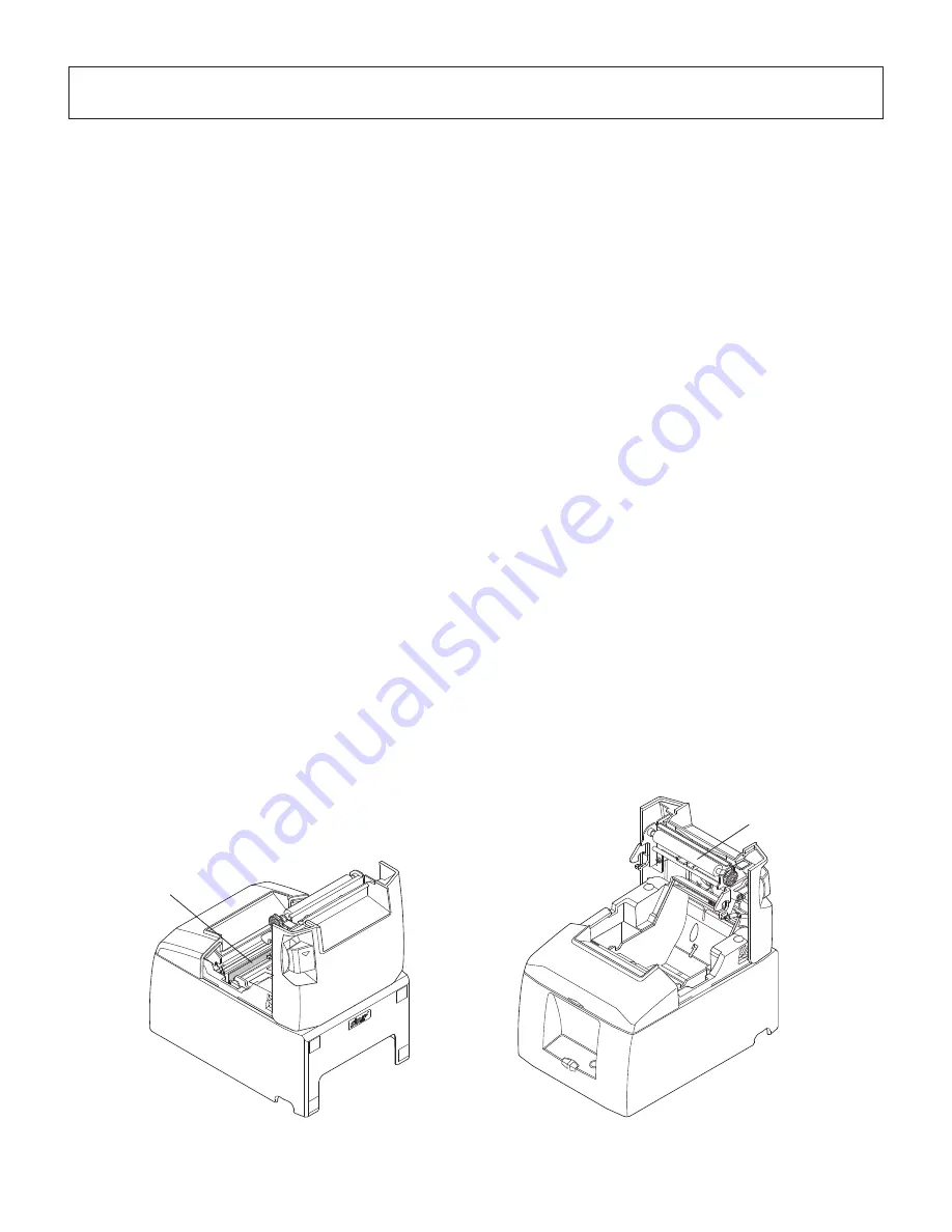
background image

– 26 –

Thermal head

Rubber roller

9. Periodical Cleaning

Printed characters may become partially unclear due to accumulated paper dust and dirt. To 
prevent such a problem, paper dust collected in the paper holder and paper transport section 
and on the surface of the thermal head must be removed periodically.
Such cleaning is recommended to be carried out once six month or one million lines.

9-1.  Cleaning the Thermal Head

To remove the dark paper dust that has accumulated on the thermal head surface, wipe it clean 
with cotton swab (or soft cloth) dipped in alcohol (ethanol, methanol, or isopropyl alcohol).

Note 1: The thermal head is easily damaged, so clean it with a soft cloth, taking care not 

to scratch it.

Note 2: Do not attempt to clean the thermal head immediately after printing, when the 

thermal head is hot.

Note 3: Beware of the risk of damaging the thermal head as a result of static electricity 

that may be created during cleaning.

Note 4: Turn the power ON only after the alcohol has dried completely.

9-2.  Cleaning the Rubber Roller

Use a dry, soft cloth to wipe off the dust that may have accumulated on the rubber roller.
Rotate the platen to clean the entire surface.

9-3.  Cleaning the Paper Holder and the Surrounding Area

Clean the paper holder of debris, dust, paper particles, glue, etc. that may have accumulated.

Содержание OKIPOS RT322

Страница 1: ...User s Guide 59317901 my okidata com RT322 RT322...

Страница 2: ...express permission is forbidden The contents of this manual are subject to change without notice All efforts have been made to ensure the accuracy of the contents of this manual at the time of going...

Страница 3: ...1 Thermal Paper Roll 17 5 2 AC adapter option 18 6 Control Panel and Other Functions 19 6 1 Control Panel 19 6 2 Errors 19 6 3 Self Printing 21 7 Adjusting the Near end Sensor 22 8 Preventing and Clea...

Страница 4: ...13 RS 232C Serial Interface 38 14 Peripheral Unit Drive Circuit 42 15 Memory Switch Settings 44 Appendix A USB Interface 45 Appendix B Ethernet Interface 47...

Страница 5: ...ies are included in the package Note The ferrite core and fastener provided with your printer depend on your printer configuration Fig 1 1 Unpacking If anything is missing contact the dealer where you...

Страница 6: ...l away from heaters and other sources of extreme heat P Make sure that the surrounding area is clean dry and free of dust P Make sure that the printer is connected to a reliable power outlet It should...

Страница 7: ...to indicate printer status and switches to operate the printer Interface connector For connection to a host computer Peripheral drive connector Connects to peripheral units such as cash drawers etc Do...

Страница 8: ...erface cable is not provided Please use a cable that meets specifications 3 2 Connecting the Interface Cable to the Printer CAUTION Before connecting disconnecting the interface cable make sure that p...

Страница 9: ...cut off any excess 5 Connect the interface cable to the connector on the rear panel of the printer 6 Fasten the connector clasps 3 2 2 RS 232C Interface Cable 1 Make sure the printer is turned off and...

Страница 10: ...er is turned off 2 Attach the ferrite core to the cable as shown in the illustration 3 Pass the cable through the cable support as shown 3 2 4 Interface Cable 1 Make sure the printer is turned off 2 A...

Страница 11: ...n below Windows 2000 Windows XP Windows Vista 32 Bit 1 Turn ON the power to your PC to start Windows 2 Insert the supplied CD ROM Drivers and Utilities into the CD ROM drive 3 Follow the instructions...

Страница 12: ...ted from the AC outlet 1 Connect the AC adapter to the power cable Note Use only the standard AC adapter and power cable 2 Connect AC adapter to the connector on the printer 3 Insert the power cable p...

Страница 13: ...ecommend that you unplug the printer from the power outlet whenever you do not plan to use it for long periods Because of this you should locate the printer so that the power outlet it is plugged into...

Страница 14: ...ur needs CAUTION Make sure that the printer is turned off and unplugged from the AC outlet and that the computer is turned off before making connections Connect the peripheral drive cable to the conne...

Страница 15: ...3 Push down both sides of the printer cover to close Note Make sure that the printer cover is securely closed 4 Tear Bar Model Tear off the paper as shown Auto Cutter Model If the printer cover is clo...

Страница 16: ...the memory switches refer to the software manual located in the Documents folders on the CD ROM 1 Insert the paper guide along the groove in the unit as shown 2 Insert the paper guide by pushing the...

Страница 17: ...damaged Do not touch them with metal objects sandpaper etc 5 Printing quality may suffer if the thermal head heating element becomes soiled by being touched with your hands Do not touch the thermal he...

Страница 18: ...the cutter is not in its home position after an error first eliminate the cause of the error then turn the power back ON 3 A margin of 5 mm or more is recommended from the end of the printed area to...

Страница 19: ...ber feet Switch cover 4 1 Attaching the Holder Plate 1 Attachtheholdingplatetotheprinter Thentighten the two screws that were supplied to secure it in place 2 Positiontheprinteroverthescrews etc onthe...

Страница 20: ...the figure Ensurethatanysoilinghasbeencompletelywiped off before attaching the rubber feet 2 Push the cover open lever and open the printer cover 3 Insert the roll paper as shown Note Depending on the...

Страница 21: ...people can not easily operate the power switch Install the switch cover as shown in the diagram below The power switch can be turned ON and OFF O by inserting a narrow instrument ball pen etc in the h...

Страница 22: ...paste or glue to secure the roll paper or its core Do not fold the tail end of the paper 2 Recommended paper Manufacturer Product name Quality characteristics Use Paper thickness m Mitsubishi Paper Mi...

Страница 23: ...ess To change the darkness settings use the printing dark ness settings command ESC RS d n or the memory switch Please consult the dealer for details 2 The print density may vary depending on the type...

Страница 24: ...aticallyrecoveredbyclos ing the printer cover Paper out error ON Flashes at 0 5 second intervals Automatically recovered by loading a new paper roll then closing the printer cover Paper near end ON Fl...

Страница 25: ...shes at 1 sec ond intervals This is not a recoverable error Head thermistor error OFF Flashes at 1 5 second intervals This is not a recoverable error Power voltage error OFF Flashes at 2 sec ond inter...

Страница 26: ...power on while holding the FEED button When the cover is closed HEX DUMP PRINTING is printed and the printer enters the Hexadecimal Dump Mode Each of the signals sent from the computer to the printer...

Страница 27: ...oll you are using 1 Open the printer cover 2 Determine the diameter of the paper roll you are using and find the required setting in the table below 3 Insert the tip of a ballpoint pen or similar obje...

Страница 28: ...1 Level 2 65 Approx 23 Approx 29 Approx 2 5 Approx 6 3 Approx 23 Approx 29 Approx 2 5 Approx 6 3 85 Approx 23 Approx 29 Approx 1 9 Approx 4 8 Approx 23 Approx 29 Approx 1 9 Approx 4 8 Notes 1 The adju...

Страница 29: ...te 1 Make sure that the paper is positioned straight If the printer cover is closed with the paper skewed a paper jam may result Note 2 Lock the printer cover by pressing down on the sides Do not try...

Страница 30: ...tter and turn it in the direction of the arrow shown on the right in order to return the cutter to its normal position 5 Opentheprintercover removeanyjammedpaper and then reinstall the paper roll 6 In...

Страница 31: ...ohol ethanol methanol or isopropyl alcohol Note 1 The thermal head is easily damaged so clean it with a soft cloth taking care not to scratch it Note 2 Do not attempt to clean the thermal head immedia...

Страница 32: ...m 5 Number of print columns 48 12 24 dots 64 9 24 dots 6 Paper feed method Friction feed 7 Paper roll Refer to chapter 5 for details on the recommended paper roll Paper width 79 5 0 5 or 57 5 0 5 mm R...

Страница 33: ...interface IEEE1284 10 4 Electrical Characteristics AC adapter 1 Input 100 to 240 V AC 50 60 Hz 2 Output DC 24 V 5 3 Current Consumption DC 24 V at room temperature Standby Approx 0 15 A ASCII printin...

Страница 34: ...ironment range 10 5 Environmental Requirements 1 Operating Temperature 5 C to 45 C Humidity 10 to 90 RH without condensation 2 Transport storage except for paper Temperature 20 C to 60 C Humidity 10 t...

Страница 35: ...CBF 60 million lines The Mean Cycle Between Failure MCBF is defined to be the overall failure cycle which includes random or wear failures that occur until the printer reaches its mechanical life of 2...

Страница 36: ...following is the procedure for changing the settings on DIP switches 1 Make sure the printer is turned off 2 Remove the screw from the DIP switch blind Then take off the DIP switch blind as shown in t...

Страница 37: ...Sensor adjustment Invalid Valid 1 5 Pin 31 INIT reset signal Valid Invalid 1 6 Handshaking conditions conditions for BUSY Offline or receive buffer full Receive buffer full 1 7 Automatic status back...

Страница 38: ...33 DIP SW 2 Switch Function ON OFF 2 1 Always ON Should be set to on 2 2 2 3 2 4 The factory settings of DIP switch are all on...

Страница 39: ...nsor adjustment Invalid Valid 1 5 Should not be changed Should be set to on 1 6 Handshaking conditions conditions for BUSY Offline or receive buffer full Receive buffer full 1 7 Automatic status back...

Страница 40: ...35 DIP SW 2 Switch Function ON OFF 2 1 Always ON Should be set to on 2 2 2 3 2 4 The factory settings of DIP switch are all on...

Страница 41: ...interface board unit Then secure it with the screws 6 Turn on the printer and all components connected to it The factory settings of DIP switch are all on except for switches 7 and 8 DIP SW 3 Switch...

Страница 42: ...Data4 Data4 7 In Out Data5 Data5 8 In Out Data6 Data6 9 In Out Data7 Data7 10 Out nAck PtrClk 11 Out Busy PtrBusy Data3 7 12 Out PError AckDataReq Data2 6 13 Out Select Xflag Data1 5 14 HostBusy 15 1...

Страница 43: ...ations 1 Data transmission method Asynchronous serial interface 2 Baud rate Selectable from 4800 9600 19200 38400 bps Refer to 11 DIP Switch Setting 3 Word length Start bit 1 bit Data bit 7 or 8 bits...

Страница 44: ...led except when transmitting data by DLE EOT and GS a B X ON X OFF communication mode Status of this signal is not checked When DIP Switch 3 7 ON This is an externally reset signal A space above 1 ms...

Страница 45: ...ata BUSY BUSY 2 During the self printing BUSY BUSY 3 When the cover is open BUSY 4 During the paper feeding by FEED button BUSY 5 When the printer stops printing due to a paper end BUSY 6 During macro...

Страница 46: ...3 2 7 8 6 5 1 4 TXD RXD RTS CTS DSR SG DCD DTR Printer side Host side 25 pin 9 pin 13 3 Cable Connections The followings are a recommended interface cable connections Note Use shielded wire less than...

Страница 47: ...circuit The recommended drive unit is shown below 6 1 1 2 3 4 5 6 F G D1 D2 TR1 TR2 TR3 R2 24 V 7824 R1 5 V M GND M GND L1 L2 6 P Modular jack connector With shield Peripheral unit Peripheral unit 2 C...

Страница 48: ...at 24V Sound pressure Min 75 dB at 1 m Lead wires red black 3 Never use the external buzzer command if you connect a device such as a cash drawer other than an external buzzer It could damage the conn...

Страница 49: ...s of memory switches please consult the dealer The table below shows the factory settings for the memory switches Memory Switch Hexadecimal Code 0 0000 1 0000 2 0000 3 0000 4 0000 5 0000 6 0000 7 0000...

Страница 50: ...o ON Note The factory settings for all the DIP swiotches is ON Appendix A USB Interface DIP SW 1 Switch Function ON OFF 1 1 Command emulation Always ON 1 2 Command emulation Always ON 1 3 Auto cutter...

Страница 51: ...loaded from http my okidata com USB Interface Specifications General Specfifications Conforms to USB 2 0 Communication Speed USB Full SPeed Mode 12 Mbps Communication Method USB Bulk Transmission Mode...

Страница 52: ...the DIP swiotches is ON Appendix B Ethernet Interface DIP SW 1 Switch Function ON OFF 1 1 Command emulation Always ON 1 2 Command emulation Always ON 1 3 Auto cutter Valid Invalid 1 4 Sensor adjustme...

Страница 53: ...ations General Specfifications Conforms to IEEEE 802 3 Communication Mode 10 Base T 100 Base T Communication Speed 0 00 Mbps Protocol TCP IP TCP IP Details ARP RARP BOOTP DHCP LPR 9100 FTP HTTP TELNET...

Отзывы: