background image

Page: 143

Service Guide ML390/391

Chapter B Illustrated Parts Listing

 
B.2.13 Packaging

Part numbers are subject to change. 

Refer to Section B.1.01

 for finding current information.

Содержание MICROLINE Turbo ML390

Страница 1: ...Thank You for purchasing this Factory Service Manual on EBAY from PCTECHINFO Click Here for more Factory Service Manuals for other Computer and Printer Copier Manufacturers from PCTECHINFO ...

Страница 2: ...l 09 17 97 Note This Adobe Acrobat version of the Okidata Service Training Manual was built with the pictures rendered at 300 dpi which is ideal for printing but does not view on most displays well Copyright 1997 Okidata Division of OKI America Inc All rights reserved See the OKIDATA Business Partner Exchange BPX for any updates to this material http bpx okidata com ...

Страница 3: ...roline 390 391 vs Microline 390 391 Plus 16 2 2 Circuit Board Description 17 Block Diagram Microline 390 391 18 Block Diagram Microline 390 391 Plus 19 2 3 Electrical Operation Initialization 20 2 3 02 Interface Control 21 2 3 03 Print Head Drive Circuit 22 2 3 04 Spacing Operation 23 2 3 05 Line Feed 24 2 3 06 Alarm Circuits 25 2 4 Mechanical Principles Of Operation Printhead 26 2 4 02 Space Mech...

Страница 4: ...ev C 54 3 2 12 Indicator Assembly Bail Bar Assembly 55 3 2 13 Head Cable Access Cover and Connection Board SRBS 56 3 2 14 Ribbon Feed Gear Assembly 57 3 2 15 Space Motor Assembly 58 3 2 16 Carriage Frame Assembly 59 3 2 17 Space Rack 60 3 2 18 Guide Rail 61 3 2 19 Platen Assembly 62 3 2 20 Line Feed Motor and Gear Line Feed Motor 63 Line Feed Motor and Gear Line Feed Motor Gear 64 3 2 21 Line Feed...

Страница 5: ...rvice Checks Index To Charts 95 4 8 02 Interconnect Diagrams Microline 390 391 Rev A and B 96 Interconnect Diagrams Microline 390 391 Rev C 97 Interconnect Diagrams Microline 390 391 Plus 98 4 8 03 Printhead 99 4 8 04 Space Motor 100 4 8 05 Line Feed Motor 101 4 8 06 Operator Panel Board 102 4 8 07 Control Board 103 4 9 Printer Tests General Information 104 4 9 02 Rolling ASCII Print Test 105 4 9 ...

Страница 6: ... General Information 126 B 1 02 Definitions of Terms 127 B 1 03 Compatibility Microline 390 391 vs Microline 390 391 Plus 128 B 1 04 Parts Ordering Information 129 B 2 Charts Index 130 B 2 01 Covers 131 B 2 02 Electrical Components Rev A and B 132 B 2 03 Electrical Components Rev C 133 B 2 04 Printer Mechanism Rev A and B 1 of 2 134 B 2 05 Printer Mechanism Rev A and B 2 of 2 135 B 2 06 Printer Me...

Страница 7: ... Fellowship Road Mount Laurel NJ 08054 3499 Fax Number 609 235 2600 ext 7034 Okilink Login Name Technical Training OKIDATA is a registered trademark of Oki Electric Industry Company Ltd marques deposee de Oki Electric Industry Company Ltd marca registrada Oki Electric Industry Company Ltd Microline is a registered trademark of Oki Electric Industry Company Ltd Centronics is a registered trademark ...

Страница 8: ... Plus can handle 80 print columns at 10 CPI The Microline 391 391 Plus can print up to 136 columns at 10 CPI The standard interface is a Centronics parallel and an optional RS232 C serial interface can be installed The optional serial interface can transfer data at speeds up to 19 2K baud Both printers feature an enhanced operator panel which provides access to the following capabilities Menu Sele...

Страница 9: ...evision Levels Microline 390 391 A Rev A units are original production units An interconnect module connects the power supply board to the main control board B Rev B units are retrofitted to include a modified interconnect module which prevents corrosion C These units have a cable connection between the power supply board and the main control board The cable connection wire replaces the interconne...

Страница 10: ...n Level 390 391A 390 391B 390 391C 390 391 Main Control Board SKRA Board 5504540 1 Main Control Board Yes Yes No No No SKRB Board 5503870 2 Main Control Board Yes Yes Yes No No SKRA 3 Board 5504540 3 Main Control Board Yes Yes Yes Yes Yes Power Supply Board PAII Board 5503880 1 Power Supply Board Yes Yes No No No SUII Board 5504740 1 Power Supply Board Yes Yes Yes Yes Yes Operator Panel Assembl y ...

Страница 11: ...CB LXSP 5504560 1 Operato r Panel Board 390 39 1 Yes Yes Yes No No PCB LXSP 5 5503860 5 Operato r Panel Board 390 39 1 Plus No No No Yes Yes Transfor mer 120 Volt XFRMR 5640720 1 Transfo rmer 390 and 390 Plu s Yes Yes Yes Yes Yes 120 Volt XFRMR 5640720 2 Transfo rmer 391 and 391 Plu s Yes Yes Yes Yes Yes 220 Volt XFRMR 5640780 1 Transfo rmer 390 and 390 Plu s Yes Yes Yes Yes No ...

Страница 12: ...1 Connec ts power supply board to main board Yes Yes No No No Cable Cable 5661680 2 Connec ts power supply board to main board No No Yes Yes Yes Cable Guide Cable Guide 5100380 1 Holds cable in place No No Yes Yes Yes Covers Cover 5348830 1 Middle Cover 390 Yes Yes Yes No No Cover 5348840 1 Middle Cover 391 Yes Yes Yes No No ...

Страница 13: ...hassis Chassis 5006110 1 Chassis Main 390 and 390 Plu s Yes Yes Yes Yes No Chassis 5006120 1 Chassis Main 391 and 391 Plu s Yes Yes Yes No Yes Copyright 1997 Okidata Division of OKI America Inc All rights reserved See the OKIDATA Business Partner Exchange BPX for any updates to this material http bpx okidata com ...

Страница 14: ...1 2 03 Character Pitches 10 CPI 12 CPI 15 CPI 17 1 CPI 20 CPI Proportional 1 2 04 Character Sets Standard ASCII Epson Character Set IBM Character Set I IBM Character Set II IBM Proprinter Compatible Character Set Foreign Language Substitution Line Graphics NOTES Characters Per Inch cpi Characters Per Second cps Dots Per Inch dpi Character Sets are selected through the Menu 1 2 05 Resident Fonts Mi...

Страница 15: ...s can access Down Line Loadable DLL fonts 1 2 06 Print Speed Print Mode Character Pitch 10 cpi 12 cpi 15 cpi 17 1cpi 20 cpi Utility 225 cps 270 cps 168 6 cps 192 9 cps 225 cps LQ 75 cps 90 cps 112 5 128 6 cps 150 cps 1 2 07 Print Resolution Print Mode Character Pitch 10 cpi 12 cpi 15 cpi 17 1cpi 20 cpi Utility 120 dpi 120 dpi 240 dpi 240 dpi 240 dpi LQ 360 dpi 360 dpi 360 dpi 360 dpi 360 dpi 1 2 0...

Страница 16: ...op Bottom Feed NOTE Bottom Feed requires the use of the optional pull tractor Line Feed Increments 1 6 1 8 n 60 n 180 n 216 and n 360 Line Feed Timing 70 ms 6 lines per inch Slew Rate 3 75 inches per second Continuous Feed Paper 1 2 11 Interface Specifications Centronics Parallel Standard RS232C Serial Optional NOTE Interface cables are sold separately A shielded cable is required Twisted pair wir...

Страница 17: ...Copyright 1997 Okidata Division of OKI America Inc All rights reserved See the OKIDATA Business Partner Exchange BPX for any updates to this material http bpx okidata com ...

Страница 18: ...orms Weight Minimum 12 pound 45 g m 2 Maximum 24 pound 90 g m 2 1 3 03 Multipart Forms Carbon Lined or Pressure Sensitive Weight Minimum 9 pound 35 g m 2 Maximum 11 pound 40 g m 2 Thickness Maximum 0 014 inches 0 356 mm Number of Copies Original plus three copies 1 3 04 Multipart Interleaf Weight Paper Minimum 10 pound 38 g m 2 Maximum 12 pound 45 g m 2 Carbon Maximum 9 pound 35 g m 2 Thickness Ma...

Страница 19: ...es x 3 5 8 inches 8 7 8 inches x 3 7 8 inches 9 1 2 inches x 4 1 8 inches 1 3 07 Envelopes Continuous NOTES Continuous Feed Envelopes should be used ONLY with bottom feed Weight Maximum 24 pound 90 g m 2 Thickness Maximum 0 014 inches 0 36 mm Width Minimum 3 inches 76 2 mm Maximum 10 inches 354 mm 1 3 08 Card Stock NOTES Card Stock should be used ONLY with bottom feed Set the head gap adjusting le...

Страница 20: ...216 mm Microline 390 390 Plus Maximum 15 inches 381 mm Microline 391 391 Plus Thickness Maximum 0 011 inches 0 28 mm 1 3 10 Transparencies Thickness Maximum 0 004 inches 0 10 mm Dimensions Maximum 8 5 inches wide x 11 inches long 216 mm x 260 mm Copyright 1997 Okidata Division of OKI America Inc All rights reserved See the OKIDATA Business Partner Exchange BPX for any updates to this material http...

Страница 21: ...b acoustic cover or paper separator Product Height Width Depth 390 390 Plus 4 6 15 7 13 6 391 391 Plus 4 6 21 7 13 6 1 4 02 Weight Microline 390 390 Plus 18 5 pounds Microline 391 391 Plus 22 3 pounds Copyright 1997 Okidata Division of OKI America Inc All rights reserved See the OKIDATA Business Partner Exchange BPX for any updates to this material http bpx okidata com ...

Страница 22: ...rements Single Phase AC Voltage 120 VAC 5 5 15 or 220 240 VAC 5 5 10 Frequency 50 60 Hz 2 1 5 02 Power Consumption Operating 110 VA Idle 40 VA Copyright 1997 Okidata Division of OKI America Inc All rights reserved See the OKIDATA Business Partner Exchange BPX for any updates to this material http bpx okidata com ...

Страница 23: ...enheit 10 to 43 degrees Celsius Storage 40 through 158 degrees Fahrenheit 40 to 70 degrees Celsius 1 6 02 Relative Humidity Operating 20 to 90 Non Operating 5 to 95 Storage 5 to 95 1 6 03 Acoustic Specifications Standard Operation 57 dba Quiet Mode 52 dba Copyright 1997 Okidata Division of OKI America Inc All rights reserved See the OKIDATA Business Partner Exchange BPX for any updates to this mat...

Страница 24: ...APPROVALS 1 7 01 Listings UL Standard No 478 Ver 5 CSA Standard C22 2 No 220 FCC Part 15 Subject J Class B Copyright 1997 Okidata Division of OKI America Inc All rights reserved See the OKIDATA Business Partner Exchange BPX for any updates to this material http bpx okidata com ...

Страница 25: ...ver 1 8 03 Cut Sheet Feeder with Access Cover CSF 3000A 1 8 04 Super Speed RS232 C Serial Interface Board 1 8 05 Memory Expansion Card Microline 390 391 Plus ONLY 32 Kbytes Character Buffer Copyright 1997 Okidata Division of OKI America Inc All rights reserved See the OKIDATA Business Partner Exchange BPX for any updates to this material http bpx okidata com ...

Страница 26: ... 9 CONSUMABLES 1 9 01 Cartridge Ribbon Black 2 million character ribbon life Re inking cartridge Copyright 1997 Okidata Division of OKI America Inc All rights reserved See the OKIDATA Business Partner Exchange BPX for any updates to this material http bpx okidata com ...

Страница 27: ...3 5 Kbytes 1 10 04 Image Buffer 13 2 Kbytes 1 10 05 Receive Buffer Epson Mode 28 Kbytes IBM Mode 16 Kbytes 1 10 06 Memory Expansion Card Option 32 Kbytes Character Buffer Microline 390 391 Plus ONLY Copyright 1997 Okidata Division of OKI America Inc All rights reserved See the OKIDATA Business Partner Exchange BPX for any updates to this material http bpx okidata com ...

Страница 28: ...nutes major sub assembly level 1 11 03 Printer Life 12 000 hrs 25 duty cycle 35 page density 1 11 04 Ribbon Life 2 million characters 1 11 05 Printhead Life 200 million characters in 10 cpi utility print quality 35 page density and 25 duty cycle Copyright 1997 Okidata Division of OKI America Inc All rights reserved See the OKIDATA Business Partner Exchange BPX for any updates to this material http...

Страница 29: ...r supply are provided Some signal names are listed with a N after them This means that the signal is active or ON when it is a logic 0 This is also indicated by a line over the signal name I PRIME Electrical Operation This section views the printer functions from an electrical perspective Mechanical Operation This section views the printer functions from a mechanical perspective Copyright 1997 Oki...

Страница 30: ...Revision Levels Microline 390 391 A Rev A units are original production units An interconnect module connects the power supply board to the main control board B Rev B units are retrofitted to include a modified interconnect module which prevents corrosion C These units have a cable connection between the power supply board and the main control board The cable connection wire replaces the interconn...

Страница 31: ...ion Level 390 391A 390 391B 390 391C 390 391 Main Control Board SKRA Board 55045401 Main Control Board Yes Yes No No No SKRB Board 55038702 Main Control Board Yes Yes Yes No No SKRA 3 Board 55045403 Main Control Board Yes Yes Yes Yes Yes Power Supply Board PAII Board 55038801 Power Supply Board Yes Yes No No No SUII Board 55047401 Power Supply Board Yes Yes Yes Yes Yes Operator Panel Assembl y ...

Страница 32: ... Yes Yes Yes No No PCB LXSP 5 55038605 Operator Panel Board 390 391 Plus No No No Yes Yes Transfor mer 120 Volt XFRMR 56407201 Transfor mer 390 and 390 Plus Yes Yes Yes Yes Yes 120 Volt XFRMR 56407202 Transfor mer 391 and 391 Plus Yes Yes Yes Yes Yes 220 Volt XFRMR 56407801 Transfor mer 390 and 390 Plus Yes Yes Yes Yes No 220 Volt XFRMR 56407802 Transfor mer 391 and 391 Plus Yes Yes Yes No Yes Int...

Страница 33: ...es Yes Cable Guide Cable Guide 51003801 Holds cable in place No No Yes Yes Yes Covers Cover 53488301 Middle Cover 390 Yes Yes Yes No No Cover 53488401 Middle Cover 391 Yes Yes Yes No No Cover 53488316 Middle Cover 390 Plus No No No Yes No Cover 53488422 Middle Cover 391 Plus No No No No Yes Chassis Chassis 50061101 Chassis Main 390 and 390 Plus Yes Yes Yes Yes No ...

Страница 34: ...Chassis Main 391 and 391 Plus Yes Yes Yes No Yes Copyright 1997 Okidata Division of OKI America Inc All rights reserved See the OKIDATA Business Partner Exchange BPX for any updates to this material http bpx okidata com ...

Страница 35: ... fuse opens to prevent damage to components in the printer Once this fuse opens the transformer MUST be replaced Filter Board The power switch line fuse and line filter are mounted on the filter board Power Supply Board This board transforms AC voltages into 5 vdc 8 vdc and 40 vdc for use throughout the printer 2 2 03 Control Board Microprocessor The microprocessor is the nucleus of the control ci...

Страница 36: ...us printing modes Motor speed and direction are determined by monitoring the signals PHASE A and PHASE B which are provided by the encoder on the spacing motor DOT Timing Generation This function generates the DOT ON signal IPT which synchronizes the print wire firing in accordance with the signals PHASE A and PHASE B This timing information is also sent to the microprocessor Q6 MSM79H048 MSM79H09...

Страница 37: ...d RAMs connected to this LSI Up to 368 kbytes of memory may be accessed Dynamic RAM D RAM Refresh CAS is used to refresh the D RAMs before the RAS refresh method is used Copyright 1997 Okidata Division of OKI America Inc All rights reserved See the OKIDATA Business Partner Exchange BPX for any updates to this material http bpx okidata com ...

Страница 38: ...hapter 2 Principles of Operation Block Diagram Microline 390 391 Copyright 1997 Okidata Division of OKI America Inc All rights reserved See the OKIDATA Business Partner Exchange BPX for any updates to this material http bpx okidata com ...

Страница 39: ...ter 2 Principles of Operation Block Diagram Microline 390 391 Plus Copyright 1997 Okidata Division of OKI America Inc All rights reserved See the OKIDATA Business Partner Exchange BPX for any updates to this material http bpx okidata com ...

Страница 40: ...ollows Q6 Q8 and Q11 are reset The operating modes of Q6 Q8 and Q11 are set Memory ROM and RAM is checked RAM is initialized Carriage homing is performed The carriage will move to the left until it contacts the left frame The program establishes the interface signals ACK BUSY and the SEL lamp lights Copyright 1997 Okidata Division of OKI America Inc All rights reserved See the OKIDATA Business Par...

Страница 41: ...the STB N signal The BUSY signal is active while this data is being processed When processing is complete the BUSY signal is turned OFF and an ACK N is sent to the host to request more data The BUSY signal is also sent to the host whenever the printer is incapable of receiving data Copyright 1997 Okidata Division of OKI America Inc All rights reserved See the OKIDATA Business Partner Exchange BPX ...

Страница 42: ...width of HD DV determines the pin drive time The pin drive time increases as the number of pins to be driven increases The pins are driven in synchronization with the signal IPT which is derived from the timing encoder PHASE A and PHASE B on the space motor Copyright 1997 Okidata Division of OKI America Inc All rights reserved See the OKIDATA Business Partner Exchange BPX for any updates to this m...

Страница 43: ... used at acceleration deceleration when a large amount torque is required The motor driver MTDV drives the space motor in accordance with the SPD A and SP ON OFF signals Pins 9 and 11 of the MTDV are the protection circuits against over voltage and over current Spacing Motor Encoder Disk Photosensor As the spacing motor is driven the signals PHASE A and PHASE B are generated by the photosensor enc...

Страница 44: ...Copyright 1997 Okidata Division of OKI America Inc All rights reserved See the OKIDATA Business Partner Exchange BPX for any updates to this material http bpx okidata com ...

Страница 45: ...ven by the phase signals LFPHA and LFPHB in synchronization with the signal LFOVD When it is not being driven the line feed motor is held in place by the LF HOLD signal Copyright 1997 Okidata Division of OKI America Inc All rights reserved See the OKIDATA Business Partner Exchange BPX for any updates to this material http bpx okidata com ...

Страница 46: ...ed on the main controller board When printhead temperature reaches approximately 90 degrees Celsius this comparator output inverts causing the HEAD TEMP signal to be sent to the motor control LSI The unit prints unidirectionally When printhead temperature reaches approximately 130 degrees Celsius the thermistor sends a signal to the main control board generating the HEAD OVERHEAT alarm Printing st...

Страница 47: ...is a spacer ring Each armature has a permanent magnet behind it The magnet attracts the armature keeping the pin inside the printhead Because of the spacer ring behind the armature ring the armature is attracted toward the permanent magnet at an angle A coil is wrapped around each permanent magnet When a dot is printed current passes through the coil creating a magnetic field which counters the ma...

Страница 48: ... the HEAD TEMP signal to be sent to the motor control LSI The unit prints unidirectionally When printhead temperature reaches approximately 130 degrees Celsius the thermistor sends a signal to the main control board generating the HEAD OVERHEAT alarm Printing stops when this alarm is detected A BUSY signal is sent to the host computer Data remains in the print buffer as long as power is supplied t...

Страница 49: ...Partner Exchange BPX for any updates to this material http bpx okidata com ...

Страница 50: ...r Encoder Disk Guide Rail Spacing Operation The printhead and spacing motor are mounted on the carriage frame The carriage frame moves along the carriage shaft space rack and guide rail The carriage shaft space rack and guide rail are parallel to the platen As the spacing motor rotates counterclockwise the carriage frame is driven to the right When the spacing motor rotates one turn the carriage f...

Страница 51: ...Copyright 1997 Okidata Division of OKI America Inc All rights reserved See the OKIDATA Business Partner Exchange BPX for any updates to this material http bpx okidata com ...

Страница 52: ...rinthead and platen when measured at the right end of the platen Turning the adjusting cam to the RIGHT will lower the right side of the guide rail This causes the printhead gap on the right side of the platen to increase Turning the adjusting cam to the LEFT will raise the right side of the guide rail This causes the printhead gap on the right side of the platen to decrease The adjusting lever de...

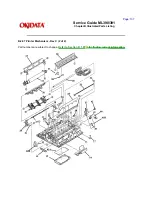
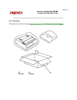
Страница 53: ...Page 29 Service Guide ML390 391 Chapter 2 Principles of Operation ...

Страница 54: ...Copyright 1997 Okidata Division of OKI America Inc All rights reserved See the OKIDATA Business Partner Exchange BPX for any updates to this material http bpx okidata com ...

Страница 55: ...uide ML390 391 Chapter 2 Principles of Operation Copyright 1997 Okidata Division of OKI America Inc All rights reserved See the OKIDATA Business Partner Exchange BPX for any updates to this material http bpx okidata com ...

Страница 56: ...to the spacing motor Ribbon Cartridge Ribbon Cartridge A uni directional feed continuous ribbon is used The ribbon is replenished by a built in ink tank in the ribbon cartridge Ribbon Feed Operation As the spacing motor rotates the ribbon gear on the spacing motor shaft turns the drive gear in the ribbon cartridge via the ribbon drive gear assembly As a result the ribbon is moved In bi directional...

Страница 57: ...Copyright 1997 Okidata Division of OKI America Inc All rights reserved See the OKIDATA Business Partner Exchange BPX for any updates to this material http bpx okidata com ...

Страница 58: ...ers friction feed rollers Pull Tractor Unit optional Paper Feed Operation The line feed motor is mounted on the left side frame of the printer It drives the platen via the reduction gear If the optional tractor unit is installed platen rotation is transmitted through the idle gear to the tractor unit The paper feed mechanism is designed so when the stepper motor rotates 48 steps 360 degrees paper ...

Страница 59: ...essure to push the pressure rollers against the platen allowing paper to be fed Tractor Feed When the release lever is set to the tractor feed position the release lever allows the reset spring to push the change gear toward the tractor gear At the same time the release lever pushes the pressure rollers away from the platen which allows paper to be fed by the push tractor ...

Страница 60: ...Copyright 1997 Okidata Division of OKI America Inc All rights reserved See the OKIDATA Business Partner Exchange BPX for any updates to this material http bpx okidata com ...

Страница 61: ...rom falling into the slot in the bottom paper guide This causes the rear part of the paper end lever to activate the paper end sensor When the printer runs out of paper the tip of the bottom paper end lever falls into the hole in the bottom paper guide The rear part of the paper end lever activates the paper end sensor An out of paper condition is detected Paper end is detected when the end of the...

Страница 62: ...Copyright 1997 Okidata Division of OKI America Inc All rights reserved See the OKIDATA Business Partner Exchange BPX for any updates to this material http bpx okidata com ...

Страница 63: ... two inches of paper SASF motion stops after two inches of paper feed motion and paper end is detected SASF should be used for loading tractor feed paper Okidata recommends using SASF instead of pressing FORM FEED Since the paper bail is opened for SASF there is less chance of jamming Copyright 1997 Okidata Division of OKI America Inc All rights reserved See the OKIDATA Business Partner Exchange B...

Страница 64: ... becomes inoperative because power is not transmitted from the platen gear through the idler and change gears to the tractor gear Cut sheets are fed by the rotation of the platen Continuous The release lever is pushed forward towards the front of the printer When the release lever is set for continuous feeding the reset spring presses the change gear in in the direction of arrow B The pin tractor ...

Страница 65: ...Copyright 1997 Okidata Division of OKI America Inc All rights reserved See the OKIDATA Business Partner Exchange BPX for any updates to this material http bpx okidata com ...

Страница 66: ...ailure analysis procedures in Section Four of this Service Handbook Follow the procedures listed in Adjustments and Service Settings Adjustments may be required when either consumables or parts are replaced Failure to perform these procedures could result in unnecessary service calls Cleaning procedures must be performed correctly if high print quality is to be achieved Copyright 1997 Okidata Divi...

Страница 67: ... removal of upper cover Cutters Feeler Gauge Large straightened Paper Clip used during printhead gap adjustment Digital Multimeter Shop Vacuum Cloth soft and lint free Cotton Swabs All purpose Cleaner Platen Cleaner Contact Kleen P N 51802301 Grease Dow Corning BR2 or equivalent Machine Oil Copyright 1997 Okidata Division of OKI America Inc All rights reserved See the OKIDATA Business Partner Exch...

Страница 68: ...tach these parts to their original positions When handling circuit boards use extreme care Integrated circuits microprocessors ROM and RAM can be destroyed by static electricity Do not place printed circuit boards directly on conductive surfaces Follow the recommended procedures when replacing assemblies and units Perform the Printhead Gap Adjustment Refer to Section 3 3 when the following occur P...

Страница 69: ...isting of the parts covered in that procedure The Okidata part number item description applicable product comment RSPL Option Consumable serial number revision level and the cross reference s to Appendix B are provided for each part Items included in the Recommended Spare Parts List are indicated by the acronym RSPL N A appears where a part number is not available Part Item Product Comment Revisio...

Страница 70: ...ne 390 391 A Rev A units are original production units An interconnect module connects the power supply board to the main control board B Rev B units are retrofitted to include a modified interconnect module which prevents corrosion C These units have a cable connection between the power supply board and the main control board The cable connection wire replaces the interconnect module Microline 39...

Страница 71: ... Main Control Board Yes Yes No No No SKRB Board 55038702 Main Control Board Yes Yes Yes No No SKRA 3 Board 55045403 Main Control Board Yes Yes Yes Yes Yes Power Supply Board PAII Board 55038801 Power Supply Board Yes Yes No No No SUII Board 55047401 Power Supply Board Yes Yes Yes Yes Yes Operator Panel Assembl y Panel Operator Assembly 50069601 Operator Panel Assembly 390 391 Yes Yes Yes No No ...

Страница 72: ...Yes Transfor mer 120 Volt XFRMR 56407201 Transfor mer 390 and 390 Plus Yes Yes Yes Yes Yes 120 Volt XFRMR 56407202 Transfor mer 391 and 391 Plus Yes Yes Yes Yes Yes 220 Volt XFRMR 56407801 Transfor mer 390 and 390 Plus Yes Yes Yes Yes No 220 Volt XFRMR 56407802 Transfor mer 391 and 391 Plus Yes Yes Yes No Yes Interconn ect Module Interconn ect Module 55328301 Connects power supply board to main bo...

Страница 73: ... Covers Cover 53488301 Middle Cover 390 Yes Yes Yes No No Cover 53488401 Middle Cover 391 Yes Yes Yes No No Cover 53488316 Middle Cover 390 Plus No No No Yes No Cover 53488422 Middle Cover 391 Plus No No No No Yes Chassis Chassis 50061101 Chassis Main 390 and 390 Plus Yes Yes Yes Yes No Chassis 50061201 Chassis Main 391 and 391 Plus Yes Yes Yes No Yes ...

Страница 74: ...Copyright 1997 Okidata Division of OKI America Inc All rights reserved See the OKIDATA Business Partner Exchange BPX for any updates to this material http bpx okidata com ...

Страница 75: ...ll RSPL A B C B 2 02 B 2 03 P N 56610801 Cord AC 220 V ML Series All Option RSPL A B C B 2 02 B 2 03 P N 56616501 Cord AC 240 V All Option A B C B 2 02 B 2 03 P N 56624101 Cord AC 220 V ML All Option A B C B 2 02 B 2 03 Right Angle P N 70000803 Kit Parallel Interface Both Option A B C D N A PlugnPlay Accessory Copyright 1997 Okidata Division of OKI America Inc All rights reserved See the OKIDATA B...

Страница 76: ...rd the rear of the printer to release it from the platen shaft 5 Remove the separator assembly NOTES The Rev A and B units used a metal ruler guide instead of the plastic separator assembly The metal ruler guide is no longer available To remove the metal ruler guide follow this procedure Open the access cover Move the paper bail lever toward the front of the printer Squeeze the retaining clips and...

Страница 77: ...Copyright 1997 Okidata Division of OKI America Inc All rights reserved See the OKIDATA Business Partner Exchange BPX for any updates to this material http bpx okidata com ...

Страница 78: ...m this procedure 3 2 01 Open the access cover 1 Remove the ribbon cartridge 2 Move the printhead mounting clamp 3 in the direction of arrow A to unlock the printhead 4 Lift and remove the printhead from the carriage frame 5 NOTE When installing the printhead push the printhead towards the platen P N 50062201 Printhead Assembly All RSPL A B C B 2 02 B 2 03 P N 52104001 Ribbon All Consumable A B C B...

Страница 79: ...Copyright 1997 Okidata Division of OKI America Inc All rights reserved See the OKIDATA Business Partner Exchange BPX for any updates to this material http bpx okidata com ...

Страница 80: ...eak Before installing the cover move the bail arm lever towards the back of the printer and move the release lever towards the front of the printer After installation verify that the cover is correctly seated in the front slots The cover will warp if it is incorrectly installed Check that the paper bail moves properly When cleaning refer to Section 3 4 of this Service Handbook P N 51901101 Knob Pl...

Страница 81: ......

Страница 82: ...Copyright 1997 Okidata Division of OKI America Inc All rights reserved See the OKIDATA Business Partner Exchange BPX for any updates to this material http bpx okidata com ...

Страница 83: ...1 3 2 04 Release the claws 1 and remove the operator panel assembly 2 from the chassis 3 As the operator panel assembly is removed it must be detached from the connector 4 on the control board 5 Release the eight claws 6 and remove the operator board 7 from the bezel 8 P N 50069601 Panel Operation w Frame Both RSPL A B C B 2 08 Assembly P N 50069610 Panel Operator Both RSPL A B C B 2 08 P N 550386...

Страница 84: ...Copyright 1997 Okidata Division of OKI America Inc All rights reserved See the OKIDATA Business Partner Exchange BPX for any updates to this material http bpx okidata com ...

Страница 85: ...rds Perform this procedure 3 2 01 3 2 04 3 2 05 Turn the locking post 1 90 degrees clockwise to unlock it Lift the locking claw 2 and pull the control board 3 away from the chassis Tilt the control board 45 degrees and remove it NOTES When installing verify that correct contacts are made at these points Guides A and B Power Interconnect Module C Linefeed Motor Interconnect Module D Sensor Lever E ...

Страница 86: ...Copyright 1997 Okidata Division of OKI America Inc All rights reserved See the OKIDATA Business Partner Exchange BPX for any updates to this material http bpx okidata com ...

Страница 87: ...es and remove it NOTE When installing verify that correct contacts are made at these points Guides A and B Linefeed Motor Interconnect Module C Sensor Lever D Printhead Cable Connector E The sensor lever must be positioned in the paper end sensor If the lever is not correctly positioned the ALARM lamp will light and the unit will not automatically load paper or receive data P N 55923901 IC CU EEPR...

Страница 88: ...Copyright 1997 Okidata Division of OKI America Inc All rights reserved See the OKIDATA Business Partner Exchange BPX for any updates to this material http bpx okidata com ...

Страница 89: ... chassis 1 and push up on the two claws 2 of the IC card B panel 3 to release the panel Pull the panel in the direction of arrow A and remove the panel P N 53490301 Panel IC Card B All RSPL A B C B 2 04 B 2 06 Copyright 1997 Okidata Division of OKI America Inc All rights reserved See the OKIDATA Business Partner Exchange BPX for any updates to this material http bpx okidata com ...

Страница 90: ...laced by the Rev C unit shown on the following pages Perform this procedure 3 2 01 3 2 04 Disconnect the cable 1 from the filter assembly Disconnect the cable 2 from the power supply board Remove the screw 3 and detach the grounding wire 4 Insert a straight slot screwdriver into the chassis from the bottom 5 shows location Push the lock spring 6 on the transformer and detach the lock spring from t...

Страница 91: ...Copyright 1997 Okidata Division of OKI America Inc All rights reserved See the OKIDATA Business Partner Exchange BPX for any updates to this material http bpx okidata com ...

Страница 92: ...grounding wire 4 Insert a straight slot screwdriver into the chassis from the bottom 5 shows location Push the lock spring 6 on the transformer and detach the lock spring from transformer clamp A 7 Lift the A side of the transformer and detach it from the transformer clamp B 8 P N 56407201 Transformer 120 V Both 90 RSPL A B C B 2 02 B 2 03 P N 56407202 Transformer 120 V Both 91 RSPL A B C B 2 02 B...

Страница 93: ...Copyright 1997 Okidata Division of OKI America Inc All rights reserved See the OKIDATA Business Partner Exchange BPX for any updates to this material http bpx okidata com ...

Страница 94: ...e filter assembly 2 Lift the AC connector 3 and the AC power switch 4 from the two guides on the main frame Remove the filter assembly The filter assembly contains a fuse 5 P N 55503101 Filter Assembly AC 120V All RSPL A B C B 2 02 B 2 03 P N 55503102 Filter 220 240 V Assembly All Option A B C B 2 02 B 2 03 Copyright 1997 Okidata Division of OKI America Inc All rights reserved See the OKIDATA Busi...

Страница 95: ...Partner Exchange BPX for any updates to this material http bpx okidata com ...

Страница 96: ...rd clamp claw 1 in the direction of arrow A Lift the B side of the power supply board 2 Detach the C side of the power supply board from the power interconnect module 3 The power supply board contains a fuse 4 P N 55047401 PCB SUII Power Supply All RSPL A B C B 2 02 B 2 03 P N 55047406 PCB SUII 6 220 24V Option A B C B 2 02 B 2 03 Power Supply P N 56616802 Cable Power Supply All RSPL C B 2 02 B 2 ...

Страница 97: ...Copyright 1997 Okidata Division of OKI America Inc All rights reserved See the OKIDATA Business Partner Exchange BPX for any updates to this material http bpx okidata com ...

Страница 98: ...e board clamp claw 1 in the direction of arrow A Lift the B side of the power supply board 2 Detach the cable from the connector 3 The power supply board contains a fuse 4 P N 55047401 PCB SUII Power Supply All RSPL A B C B 2 02 B 2 03 P N 55047406 PCB SUII 6 220 24V Option A B C B 2 02 B 2 03 Power Supply P N 56616802 Cable Power Supply All RSPL C B 2 02 B 2 03 Nylon Connector ...

Страница 99: ...Copyright 1997 Okidata Division of OKI America Inc All rights reserved See the OKIDATA Business Partner Exchange BPX for any updates to this material http bpx okidata com ...

Страница 100: ... printers do NOT have a cable guide The Rev C printers do NOT have a power interconnect module Rev C printers have a cable guide Perform these procedures 3 2 01 3 2 04 Use a straight slot screwdriver to release the claws 1 from the chassis clamps 2 Remove the power interconnect module 3 P N 53328301 Module Power Interconnect Both RSPL A B B 2 04 ...

Страница 101: ...Copyright 1997 Okidata Division of OKI America Inc All rights reserved See the OKIDATA Business Partner Exchange BPX for any updates to this material http bpx okidata com ...

Страница 102: ...o NOT have a cable guide The Rev C printers do NOT have a power interconnect module Rev C printers have a cable guide Perform these procedures 3 2 01 3 2 04 Use a straight slot screwdriver to release the claws 1 from the chassis clamps 2 Remove the cable guide 3 P N 51003801 Guide Cable All RSPL C B 2 06 ...

Страница 103: ...Copyright 1997 Okidata Division of OKI America Inc All rights reserved See the OKIDATA Business Partner Exchange BPX for any updates to this material http bpx okidata com ...

Страница 104: ...r from the right bail arm 6 Use needle nose pliers to remove the right bail arm spring 7 Release the claw 8 and detach the right bail arm from the bail bar Pull the right bail arm through the guide hole 9 in the chassis and remove the arm P N 50911801 Spring Bail Arm L All RSPL A B C B 2 04 B 2 06 P N 53489301 Bail Arm L All RSPL A B C B 2 04 B 2 06 P N 50911701 Spring Bail Arm R All RSPL A B C B ...

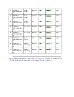
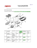
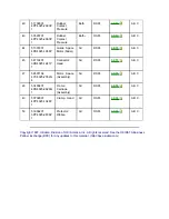
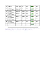
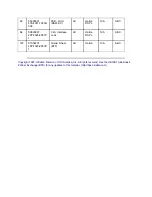
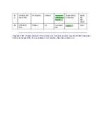
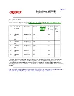
Страница 105: ...Copyright 1997 Okidata Division of OKI America Inc All rights reserved See the OKIDATA Business ...

Страница 106: ...Partner Exchange BPX for any updates to this material http bpx okidata com ...

Страница 107: ...f arrow A Pull the connector 2 in the direction of arrow B and remove the connector Release the clamp 3 and detach the head cable 4 Release the two claws 5 and remove the head cable access cover 6 The claws are accessed from the bottom of the printer Pull the board 7 in the direction of arrow B to detach it from the claws 8 Remove the board P N 56723801 Conn Connection AKT 60 All RSPL B 2 04 P N 5...

Страница 108: ...Copyright 1997 Okidata Division of OKI America Inc All rights reserved See the OKIDATA Business Partner Exchange BPX for any updates to this material http bpx okidata com ...

Страница 109: ...o rear claws 3 of the ribbon feed gear assembly 4 Lift and remove the assembly Detach the head cable 5 the cable clamp not shown and the contact pressure rubber 6 from the assembly NOTE Lubrication When lubricating refer to Section 3 5 of this Service Handbook P N 50061401 Gear Ribbon Feed Assembly All RSPL A B C B 2 09 P N 56615403 Cable Head Flexible Both 90 RSPL A B C B 2 09 P N 56615404 Cable ...

Страница 110: ......

Страница 111: ...Copyright 1997 Okidata Division of OKI America Inc All rights reserved See the OKIDATA Business Partner Exchange BPX for any updates to this material http bpx okidata com ...

Страница 112: ...r first The contact side of the head cable faces down when the carriage cable is inserted into the connector on the space motor assembly Work the cable from side to side until it is fully seated in the connector No contacts should be visible Perform the printhead gap adjustment after installing this assembly Refer to Section 3 3 of this Service Handbook for details Cleaning When cleaning refer to ...

Страница 113: ...Copyright 1997 Okidata Division of OKI America Inc All rights reserved See the OKIDATA Business Partner Exchange BPX for any updates to this material http bpx okidata com ...

Страница 114: ...e the carriage shaft with the carriage frame 5 Slide the carriage frame off the carriage shaft NOTES Installation Perform the printhead gap adjustment after installing this assembly Refer to Section 3 3 of this Service Handbook for details Cleaning When cleaning refer to Section 3 4 of this Service Handbook Lubrication When lubricating refer to Section 3 5 of this Service Handbook P N 51109401 Sha...

Страница 115: ......

Страница 116: ...Copyright 1997 Okidata Division of OKI America Inc All rights reserved See the OKIDATA Business Partner Exchange BPX for any updates to this material http bpx okidata com ...

Страница 117: ...he space rack NOTES Installation Fully seat the two guide pins 5 Cleaning When cleaning refer to Section 3 4 of this Service Handbook CAUTION Lubrication Do NOT lubricate the space rack Lubricating the space rack will attract dust If enough dust accumulates on the space rack printing problems will occur P N 53489401 Rack Space Both 90 RSPL A B C B 2 04 B 2 06 P N 53489402 Rack Space Both 91 RSPL A...

Страница 118: ...Copyright 1997 Okidata Division of OKI America Inc All rights reserved See the OKIDATA Business Partner Exchange BPX for any updates to this material http bpx okidata com ...

Страница 119: ...he claw 3 in the direction of arrow A to disengage the guide rail 4 at position B Pull the guide rail in the direction of arrow C to release it from the guide 5 in the chassis Lift and remove the guide rail NOTE After installing the guide rail check the printhead gap adjustment Refer to Section 3 3 of this Service Handbook P N 51002101 Rail Guide Both 90 RSPL A B C B 2 04 B 2 06 P N 51002102 Rail ...

Страница 120: ...Copyright 1997 Okidata Division of OKI America Inc All rights reserved See the OKIDATA Business Partner Exchange BPX for any updates to this material http bpx okidata com ...

Страница 121: ...front of the printer as far as it will go Set the platen assembly into place Verify that the bias gear securely engages the line feed motor gear Secure the two lock levers Set the release lever to OPEN front and check that the groove of the paper chute firmly engages with the groove of the main chassis Cleaning When cleaning refer to Section 3 4 of this Service Handbook Lubrication When lubricatin...

Страница 122: ...Copyright 1997 Okidata Division of OKI America Inc All rights reserved See the OKIDATA Business Partner Exchange BPX for any updates to this material http bpx okidata com ...

Страница 123: ...traight slot screwdriver to remove the clip 1 Use a straight slot screwdriver to open the lock levers 2 and push the bracket 3 of the line feed motor 4 in the direction of arrow A Remove the line feed motor from the guides 5 CAUTION Installation If the line feed motor assembly is not correctly installed excessive wear of the platen gears will occur Verify that the tabs are not bent If the tabs are...

Страница 124: ...Copyright 1997 Okidata Division of OKI America Inc All rights reserved See the OKIDATA Business Partner Exchange BPX for any updates to this material http bpx okidata com ...

Страница 125: ...the gear into the groove of the shaft Rotate the bias gear towards the front of the printer as far as the gear will turn This aligns the bias gear with the platen gear Set the platen assembly in place securely engaging the line feed motor gear with the platen gears CAUTION If the claws do not lock into the groove of the support shaft the gear will walk off the shaft during use Verify that the line...

Страница 126: ...Copyright 1997 Okidata Division of OKI America Inc All rights reserved See the OKIDATA Business Partner Exchange BPX for any updates to this material http bpx okidata com ...

Страница 127: ...s 3 2 01 3 2 02 3 2 04 3 2 05 3 2 06 3 2 20 Insert a straight slot screwdriver between the line feed motor interconnect module 1 and the chassis Then carefully pry the module from the two guide holes 2 P N 53328401 Module LF Motor Interconnect All RSPL A B C B 2 05 B 2 07 Copyright 1997 Okidata Division of OKI America Inc All rights reserved See the OKIDATA Business Partner Exchange BPX for any up...

Страница 128: ... Slide the spring out in the direction of arrow B Detach the change gear 2 Detach the idler gear 3 NOTE Lubrication When lubricating refer to Section 3 5 of this Service Handbook Parts Replacement The Kit Idler Change Gear ML300 includes the change and idler gears Order this kit when replacing these parts P N 50912001 Spring Reset All RSPL A B C B 2 05 B 2 07 P N 58227501 Kit Idler Change Gear All...

Страница 129: ...Copyright 1997 Okidata Division of OKI America Inc All rights reserved See the OKIDATA Business Partner Exchange BPX for any updates to this material http bpx okidata com ...

Страница 130: ...se the claw 1 from the guide 2 in the chassis Pull the release lever 3 in the direction of arrow A and remove the lever P N 53489501 Lever Release All RSPL A B C B 2 05 B 2 07 Copyright 1997 Okidata Division of OKI America Inc All rights reserved See the OKIDATA Business Partner Exchange BPX for any updates to this material http bpx okidata com ...

Страница 131: ...from the projections 5 on the chassis Remove the paper pressure guide 6 NOTE When installing the paper pressure guide be sure to fit it into the projections 5 and guide plates 7 at the same time The Microline 390 390 Plus has five coupling holes and ten guide plates The Microline 391 391 Plus has seven coupling holes and thirteen guide plates P N 50911501 Guide Paper Pressure Both 90 RSPL A B C B ...

Страница 132: ......

Страница 133: ...Copyright 1997 Okidata Division of OKI America Inc All rights reserved See the OKIDATA Business Partner Exchange BPX for any updates to this material http bpx okidata com ...

Страница 134: ...Refer to View B for the correct position If the paper end lever is incorrectly positioned paper jams no paper end indications will occur Position the tab of the paper chute firmly with the groove of the main frame Engage the cut sheet paper end lever attached to the bottom of the paper chute to the bottom paper end lever under the main frame Then install the paper chute P N 50061801 Chute Paper As...

Страница 135: ...Copyright 1997 Okidata Division of OKI America Inc All rights reserved See the OKIDATA Business Partner Exchange BPX for any updates to this material http bpx okidata com ...

Страница 136: ...left tractor assembly the sheet guide 13 and the right tractor assembly NOTES Installation The tractors must be synchronized The pins 14 on the left and right tractors must be aligned when installed Also verify that the guide holes 15 in the tractor drive gears are facing the same direction The left tractor assembly must be positioned to the left line feed motor side of the plastic tab and ground ...

Страница 137: ...Copyright 1997 Okidata Division of OKI America Inc All rights reserved See the OKIDATA Business Partner Exchange BPX for any updates to this material http bpx okidata com ...

Страница 138: ...ever 1 clockwise until it is horizontal Lift the sensor lever from the shaft bearing 2 Work the sensor lever from the guide hole 3 in the chassis and remove the lever P N 53489001 Lever Sensor All RSPL A B C B 2 05 B 2 07 Copyright 1997 Okidata Division of OKI America Inc All rights reserved See the OKIDATA Business Partner Exchange BPX for any updates to this material http bpx okidata com ...

Страница 139: ... 02 3 2 04 3 2 05 3 2 06 3 2 20 3 2 22 3 2 25 3 2 26 3 2 27 While pushing on the six claws 1 detach the sensor cover 2 Four of the six claws are visible in the illustration Lift the paper end B lever 3 from the chassis P N 53488901 Lever Paper End B Both 90 RSPL A B C B 2 05 B 2 07 P N 53488902 Lever Paper End B Both 91 RSPL A B C B 2 05 B 2 07 P N 53489101 Cover Sensor All RSPL A B C B 2 05 B 2 0...

Страница 140: ...Copyright 1997 Okidata Division of OKI America Inc All rights reserved See the OKIDATA Business Partner Exchange BPX for any updates to this material http bpx okidata com ...

Страница 141: ...to reach the main chassis assembly 1 P N 50061101 Chassis Main Assembly Both 90 RSPL A B C B 2 05 B 2 07 P N 50061201 Chassis Main Assembly Both 91 RSPL A B C B 2 05 B 2 07 Copyright 1997 Okidata Division of OKI America Inc All rights reserved See the OKIDATA Business Partner Exchange BPX for any updates to this material http bpx okidata com ...

Страница 142: ...e 391 Plus printers This procedure may be required when replacing either consumables or parts The disassembly assembly procedures list the required adjustment and refer you to this section Failure to perform these procedures may result in unnecessary service calls Copyright 1997 Okidata Division of OKI America Inc All rights reserved See the OKIDATA Business Partner Exchange BPX for any updates to...

Страница 143: ...of the platen is modified by turning the adjust screw Turning the adjust screw varies the vertical position of the space motor Parallel Adjustment Phase Steps 10 12 The adjust cam lever is moved to ensure that the printhead moves parallel to the platen Verification Phase Steps 13 14 This phase verifies that the Parallel Adjustment Phase did not affect the Printhead Gap Modification Phase To adjust...

Страница 144: ...b side of the platen 11 Use a feeler gauge to check the printhead gap The printhead gap must measure 0 016 inch 0 002 inch 0 41 mm 0 05 mm 12 If the gap measurements are different between the left and right positions turn the adjust cam Turning the adjust cam adjusts the height of the ruler guide Turn CLOCKWISE to increase the printhead gap The guide rail is lowered Turn COUNTER CLOCKWISE to decre...

Страница 145: ...Copyright 1997 Okidata Division of OKI America Inc All rights reserved See the OKIDATA Business Partner Exchange BPX for any updates to this material http bpx okidata com ...

Страница 146: ...ill require more frequent cleaning Excessive lubricant attracts dust and accumulations build up quickly Keeping the covers in place and performing the cleaning procedures correctly will help ensure the highest quality printer output 3 4 02 Cleaning Schedule Routine inspection and cleaning should be performed as listed below Every six months or 300 hours of operation 3 4 03 Cleaning Tools Soft Lint...

Страница 147: ...Cloth All purpose cleaner Remove any paper particles Wipe or vacuum all dirt dust etc Space Rack 3 2 17 Vacuum Cloth Remove any paper particles Wipe or vacuum all dirt dust etc Paper End Sensor 3 2 28 Vacuum Cloth Wipe or vacuum any accumulated dust from the sensor Platen 3 2 29 Cloth Platen Cleaner Wipe the surface of the platen with platen cleaner Copyright 1997 Okidata Division of OKI America I...

Страница 148: ...s or 300 hours of operation or When a part on the lubrication schedule is replaced 3 5 03 Lubrication Types Grease Dow Corning BR2 or equivalent Machine Oil 10 30 weight 3 5 04 Lubrication Amounts Do NOT over lubricate the printer Operational problems are caused by excess lubricant The excess lubricant causes dust to accumulate These accumulations can jam gears or cause print problems The Lubricat...

Страница 149: ... 16 Machine Oil Small Place a small amount on the surface of the carriage shaft Wipe with a soft lint free cloth Platen Assembly Contact point between the bias gear and the platen gear 3 2 19 Machine Oil Small Idle Gear Bearing 3 2 22 Grease Medium Change Lever Bearing and pivot point 3 2 22 Grease Medium Pressure Spring Pivot point of the release cam Holders on the pressure spring Bearing of the ...

Страница 150: ...ber Face Pressure Roller Rubber Face Tractor Pins Space Motor Board Electrical Contacts and Connections Space Rack Head Cable Microswitches Pressure Rollers on Bail Bar Copyright 1997 Okidata Division of OKI America Inc All rights reserved See the OKIDATA Business Partner Exchange BPX for any updates to this material http bpx okidata com ...

Страница 151: ... your next course of action Use the RAP Index to identify which RAP should be used to resolve the problem with the machine If you encounter a situation that is not addressed by the documentation in this kit please report the problem to Okidata Send your report to the Okidata Technical Training Group Refer to the Service Center Reference Guide for information on contacting Okidata The following inf...

Страница 152: ...Revision Levels Microline 390 391 A Rev A units are original production units An interconnect module connects the power supply board to the main control board B Rev B units are retrofitted to include a modified interconnect module which prevents corrosion C These units have a cable connection between the power supply board and the main control board The cable connection wire replaces the interconn...

Страница 153: ...ion Level 390 391A 390 391B 390 391C 390 391 Main Control Board SKRA Board 55045401 Main Control Board Yes Yes No No No SKRB Board 55038702 Main Control Board Yes Yes Yes No No SKRA 3 Board 55045403 Main Control Board Yes Yes Yes Yes Yes Power Supply Board PAII Board 55038801 Power Supply Board Yes Yes No No No SUII Board 55047401 Power Supply Board Yes Yes Yes Yes Yes Operator Panel Assembl y ...

Страница 154: ... Yes Yes Yes No No PCB LXSP 5 55038605 Operator Panel Board 390 391 Plus No No No Yes Yes Transfor mer 120 Volt XFRMR 56407201 Transfor mer 390 and 390 Plus Yes Yes Yes Yes Yes 120 Volt XFRMR 56407202 Transfor mer 391 and 391 Plus Yes Yes Yes Yes Yes 220 Volt XFRMR 56407801 Transfor mer 390 and 390 Plus Yes Yes Yes Yes No 220 Volt XFRMR 56407802 Transfor mer 391 and 391 Plus Yes Yes Yes No Yes Int...

Страница 155: ...es Yes Cable Guide Cable Guide 51003801 Holds cable in place No No Yes Yes Yes Covers Cover 53488301 Middle Cover 390 Yes Yes Yes No No Cover 53488401 Middle Cover 391 Yes Yes Yes No No Cover 53488316 Middle Cover 390 Plus No No No Yes No Cover 53488422 Middle Cover 391 Plus No No No No Yes Chassis Chassis 50061101 Chassis Main 390 and 390 Plus Yes Yes Yes Yes No ...

Страница 156: ...Chassis Main 391 and 391 Plus Yes Yes Yes No Yes Copyright 1997 Okidata Division of OKI America Inc All rights reserved See the OKIDATA Business Partner Exchange BPX for any updates to this material http bpx okidata com ...

Страница 157: ...Refer to the Service Center Reference Guide for information on accessing Okilink II 4 2 03 Faxable Facts Okidatas Faxable Facts is an automated fax document retrieval system It is maintained by Okidatas Customer Information Center Answers to common questions about Okidata products are available through Faxable Facts Refer to the Service Center Reference Guide for information on accessing Faxable F...

Страница 158: ...equests Okilink II provides round table discussions on technical problems Errors and corrections in the training materials are listed in the Training Section of Okilink II The Technical Service Bulletins also known as Okidata s Monthly Mail are available via Okilink II Situations that are not addressed in the reference documentation technical service bulletins or round tables may be reported to th...

Страница 159: ...ountry Telephone and Fax Numbers with area country access codes Product Name Units Serial Number Firmware Revision Level Description of Problem Document Name with page number or procedure with error or problem Copyright 1997 Okidata Division of OKI America Inc All rights reserved See the OKIDATA Business Partner Exchange BPX for any updates to this material http bpx okidata com ...

Страница 160: ...when the printer is powered ON Make sure the printer is plugged in Check the power cord connection to the printer and the outlet If a power strip is being used make sure the strip is powered ON The ALARM lamp is lit The printer may be out of paper or the paper may have jammed The SEL lamp will not light After loading paper press the SEL switch If the ALARM lamp does not go out after paper is loade...

Страница 161: ...de panel or menu settings Check the word processors manual to see if the initialization string can be modified If so remove any codes that interfere with the printers settings The PRINT QUALITY CHARACTER PITCH and MODE switches do not work The Operator Panel Functions Item in the Printer Menu can be set to enable FULL OPERATION or disable LIMITED OPERATION these features If the printer is part of ...

Страница 162: ...n Line The printer is ready to receive data and to print OFF ON N A Normal Operation Hex Dump The printer is in Hex Dump Mode Refer to Section 4 7 OFF OFF N A Normal Operation Off Line The printer will NOT receive data or print OFF OFF ON Normal Operation Menu Mode The operator may view or change the menu settings ON OFF N A Operator Alarm Paper End Printer is out of paper ON OFF N A Operator Alar...

Страница 163: ...nter is ready to receive data and to print OFF ON N A Normal Operation Hex Dump The printer is in Hex Dump Mode Refer to Section 4 7 OFF OFF N A Normal Operation Off Line The printer will NOT receive data or print OFF OFF ON Normal Operation Menu Mode The operator may view or change the menu settings ON OFF N A Operator Alarm Paper End Printer is out of paper ON OFF N A Operator Alarm Paper Jam Th...

Страница 164: ...y board Rev A and B units ONLY Clean the contacts if dirty If contacts are bent or broken replace the module Proper inspection and cleaning of the power interconnect module contacts can eliminate a false diagnosis of a failed control board or power supply board Check the contacts and connections of the control board If good contact is not made at all connections and ground points false diagnosis w...

Страница 165: ... O N ON Cartridge CG Error 1 Reinsert the font card 2 Replace the font card 3 Replace the main control board Blinking O N O N Head Homing Error Refer to RAP 02 Blinking O N ON Spacing Error Refer to RAP 02 Blinking O N ON Resident CG Release Replace the main control board Blinking O N ON Cartridge CG Release 1 Reinsert the font card 2 Replace the font card 3 Replace the main control board ...

Страница 166: ...PR OP Courie r Roma n Helv ette Orator Error Conditi on Action Blinking ON ON Internal RAM Error Replace the main control board Blinking ON ON Serial I F Connec tion Error 1 Reinstall the serial interface 2 Replace the serial i f 3 Replace the main control board Blinking ON ON Serial I F Time Out Error 1 Replace the serial i f 2 Replace the main control board Blinking ON ON Progra m ROM Error 1 Re...

Страница 167: ...side nt CG Error Replace the main control board Blinking O N ON Externa l RAM Error 1 Reinsert the RAM card 2 Replace the RAM card 3 Replace the main control board Blinking O N ON RAM Card Error 1 Reinsert the RAM card 2 Replace the RAM card 3 Replace the main control board Blinking O N ON Head Homing Error Refer to RAP 02 Blinking O N ON Spacing Error Refer to RAP 02 ...

Страница 168: ...nd Respon se Error Replace the main control board Blinking ON ON Call Put Replace the main control board Blinking ON ON ON Call Get Replace the main control board Blinking ON ON ON HPC LPC FIFO Replace the main control board Copyright 1997 Okidata Division of OKI America Inc All rights reserved See the OKIDATA Business Partner Exchange BPX for any updates to this material http bpx okidata com ...

Страница 169: ...inters problem Go to the appropriate RAP All of the RAPs will begin with a START Statement followed by questions or another type of statement If the RAPs do not lead you to the cause of a problem please report this to Okidata Refer to Section 4 3 for further details Copyright 1997 Okidata Division of OKI America Inc All rights reserved See the OKIDATA Business Partner Exchange BPX for any updates ...

Страница 170: ...3 Wrong or Missing Characters Dots on Output 04 Line Feed Problems 05 Malfunction of Operator Panel Switch es 06 Parallel Interface Does Not Receive Data 07 Serial Interface Does Not Receive Data Copyright 1997 Okidata Division of OKI America Inc All rights reserved See the OKIDATA Business Partner Exchange BPX for any updates to this material http bpx okidata com ...

Страница 171: ...en replace the module Proper inspection and cleaning of the power interconnect module contacts can eliminate a false diagnosis of a failed control board or power supply board Control Board Check the contacts and connections of the control board If good contact is not made at all connections and ground points false diagnosis will occur Copyright 1997 Okidata Division of OKI America Inc All rights r...

Страница 172: ...e holder is making proper contact with the fuse Remove the fuse from the holder Gently squeeze both sides of the holder slightly towards each other Reinsert the fuse Is the problem resolved YES End of procedure NO Are 5 vdc and 40 vdc supplied to the control board 5 vdc Take the voltage reading between Pin 6 and Pin 9 of CN2 on the power supply board 40 vdc Take the voltage reading between Pin 1 a...

Страница 173: ... YES Go to E E Replace the connector between the power supply board and the control board Is the problem resolved YES End of procedure NO Replace the power supply board Is the problem resolved YES End of procedure NO Contact Technical Support Copyright 1997 Okidata Division of OKI America Inc All rights reserved See the OKIDATA Business Partner Exchange BPX for any updates to this material http bp...

Страница 174: ...een the carriage cable and the space motor contacts Is the problem resolved YES End of procedure NO Go to B B Is the carriage assembly jammed YES Clean the teeth of the space motor and the space rack Is the problem resolved YES End of procedure NO Go to C NO Go to C C Are 5 vdc and 40 vdc being supplied to the control board 5 vdc Voltage is read between Pin 6 and Pin 9 of CN2 on the power supply b...

Страница 175: ...y inserted into CN2 of the control board NO Properly insert the cable Is the problem resolved YES End of procedure NO Go to the next step listed below YES Replace the control board Is the problem resolved YES End of procedure NO Replace the space motor Is the problem resolved YES End of procedure NO Contact Technical Support Copyright 1997 Okidata Division of OKI America Inc All rights reserved Se...

Страница 176: ...cable Is the problem resolved YES End of procedure NO Go to the next step listed below YES Go to the next step listed below YES Replace the printhead Is the problem resolved YES End of procedure NO Replace the control board Is the problem resolved YES End of procedure NO Go to A A Are the contacts between the space motor and the carriage cable properly made YES Replace the space motor Is the probl...

Страница 177: ...Copyright 1997 Okidata Division of OKI America Inc All rights reserved See the OKIDATA Business Partner Exchange BPX for any updates to this material http bpx okidata com ...

Страница 178: ...g between steps 1 Check the paper feed path setting 2 Clean the platen gear idle gear and drive gear 3 Verify that the platen gear idle gear and drive gear are correctly meshing 4 Verify that the left and right push tractor assemblies are correctly installed 5 Verify that the left and right push tractor assemblies are correctly operating Replace if necessary Is the problem resolved YES End of proc...

Страница 179: ...ort NO Correct the contact Is the problem resolved YES End of procedure NO Contact Technical Support Copyright 1997 Okidata Division of OKI America Inc All rights reserved See the OKIDATA Business Partner Exchange BPX for any updates to this material http bpx okidata com ...

Страница 180: ... of procedure NO Replace the control board Is the problem resolved YES End of procedure NO Contact Technical Support NO Correctly make the connection Is the problem resolved YES End of procedure NO Replace the control board Is the problem resolved YES End of procedure NO Contact Technical Support Copyright 1997 Okidata Division of OKI America Inc All rights reserved See the OKIDATA Business Partne...

Страница 181: ...e cable Is it correctly connected YES Replace the cable with a cable known to work Is the problem resolved YES End of procedure NO Replace the control board Is the problem resolved YES End of procedure NO Call Technical Support NO Correctly connect the cable Is the problem resolved YES End of procedure NO Replace the control board Is the problem resolved YES End of procedure NO Call Technical Supp...

Страница 182: ...terface cable with a cable proven to work Is the problem resolved YES Replace the cable NO Perform the Serial Loopback Test Refer to Section 4 9 of this Service Handbook Do the memory buffer and interface tests pass NO Replace the serial interface board Is the problem resolved YES End of procedure NO Go to the next step listed below YES Check the connection between the serial interface board and t...

Страница 183: ...hile powering ON the printer The printer will remain in hexadecimal dump mode until it is powered OFF 4 7 03 Sample Here is a line of BASIC code LPRINT CHR 27 0 CHR 30 This is an example of a hexadecimal dump In hexadecimal dump mode the BASIC code line would print as follows This is an example of a hexadecimal dump 1B 30 1E 54 68 69 73 20 69 73 20 61 6E 20 65 78 0 61 6D 70 6C 65 20 6F 66 20 61 20...

Страница 184: ...Interconnect Diagram Microline 390 391 Rev A and B Rev C Microline 390 391 Plus Printhead Space Motor Line Feed Motor Control Board Microline 390 391 Rev A and B Rev C Microline 390 391 Plus Operator Panel Board Copyright 1997 Okidata Division of OKI America Inc All rights reserved See the OKIDATA Business Partner Exchange BPX for any updates to this material http bpx okidata com ...

Страница 185: ...re Repair Analysis 4 8 02 Interconnect Diagrams Microline 390 391 Rev A and B Copyright 1997 Okidata Division of OKI America Inc All rights reserved See the OKIDATA Business Partner Exchange BPX for any updates to this material http bpx okidata com ...

Страница 186: ...91 Chapter 4 Failure Repair Analysis Microline 390 391 Rev C Copyright 1997 Okidata Division of OKI America Inc All rights reserved See the OKIDATA Business Partner Exchange BPX for any updates to this material http bpx okidata com ...

Страница 187: ...91 Chapter 4 Failure Repair Analysis Microline 390 391 Plus Copyright 1997 Okidata Division of OKI America Inc All rights reserved See the OKIDATA Business Partner Exchange BPX for any updates to this material http bpx okidata com ...

Страница 188: ...l Name Connection Refer to Interconne ct Diagram Coil Resista nce Figure A B C D E Print head Odd En 2 3 13 15 13 Pins on front of printhead Even En 2 3 13 15 15 Headgap 7 2 2 Odd Common 8 12 3 6 5 6 14 15 30 31 Even Common 8 12 3 6 3 4 6 7 26 27 TSD 14 10 10 20 S Clock 15 11 11 S Data 17 14 14 ...

Страница 189: ...s Pins on back of printhead Pin 2 2 2 Pin 3 18 18 Pin 4 3 3 Pin 5 35 39 Pin 6 22 22 Pin 7 34 38 Pin 8 23 23 Pin 9 17 17 Pin 10 4 4 Pin 11 16 16 Pin 12 5 5 Pin 13 33 33 Pin 14 24 24 Pin 15 32 32 Pin 16 25 25 Pin 17 13 13 Pin 18 8 8 Pin 19 12 23 Pin 20 9 9 Pin 21 11 11 Pin 22 10 10 Pin 23 29 29 ...

Страница 190: ...Pin 24 28 28 Copyright 1997 Okidata Division of OKI America Inc All rights reserved See the OKIDATA Business Partner Exchange BPX for any updates to this material http bpx okidata com ...

Страница 191: ...ion Refer to Interconnect Diagram Coil Resistance A B C Space Motor U 5 7 7 Approx 21 ohms V 13 8 8 W 4 9 9 Phase A 20 18 18 Phase B 19 17 17 Copyright 1997 Okidata Division of OKI America Inc All rights reserved See the OKIDATA Business Partner Exchange BPX for any updates to this material http bpx okidata com ...

Страница 192: ...tor Name Signal Name Connection Refer to Interconnect Diagram Coil Resistance Line Feed Motor Phase 1 2 1 Phase 2 3 4 Copyright 1997 Okidata Division of OKI America Inc All rights reserved See the OKIDATA Business Partner Exchange BPX for any updates to this material http bpx okidata com ...

Страница 193: ...onnection Refer to Interconnect Diagram F Op Panel SEL 3 MODE 4 LF 5 FF 6 PARK 7 TOF 13 PRINT 10 FONT 11 CHAR 12 SD CLK 14 SD 2 5 V 1 15 0 V 8 9 Copyright 1997 Okidata Division of OKI America Inc All rights reserved See the OKIDATA Business Partner Exchange BPX for any updates to this material http bpx okidata com ...

Страница 194: ...nal Name Connection Refer to Interconnect Diagram H Control Board CN5 40 V 1 3 EP 4 5 5 V 6 7 0 V 8 9 8 V 10 AC 10 V 11 ALM 12 Copyright 1997 Okidata Division of OKI America Inc All rights reserved See the OKIDATA Business Partner Exchange BPX for any updates to this material http bpx okidata com ...

Страница 195: ...t Serial Interface Loopback Test The Rolling ASCII Print and Font Sample Tests are used to determine if the printer is operating properly The Serial Interface Loopback Test is used to test proper operation of the Serial Interface Board Copyright 1997 Okidata Division of OKI America Inc All rights reserved See the OKIDATA Business Partner Exchange BPX for any updates to this material http bpx okida...

Страница 196: ...r Model Emulation Country Code and Firmware Revision Level CAUTION If 13 6 inch Paper Width is selected in the menu and you run this test with 8 5 inch wide paper loaded the test will print on the platen This may damage the platen ribbon and printhead Set the paper width to 8 5 inches before running this test Procedure Verify that the printer is loaded with paper and that the paper is the correct ...

Страница 197: ...Copyright 1997 Okidata Division of OKI America Inc All rights reserved See the OKIDATA Business Partner Exchange BPX for any updates to this material http bpx okidata com ...

Страница 198: ...print on the platen This may damage the platen ribbon and printhead Set the paper width to 8 5 inches before running this test Procedure Verify that the printer is loaded with paper Power OFF the printer Press and hold the LINE FEED switch while powering ON the printer If the font sample test does not print after you power ON the printer you may have released the LINE FEED switch too soon This is ...

Страница 199: ...Copyright 1997 Okidata Division of OKI America Inc All rights reserved See the OKIDATA Business Partner Exchange BPX for any updates to this material http bpx okidata com ...

Страница 200: ... the current group Press ITEM until you access the desired item Diagnostic Test Press SET until you access the desired setting YES Press MODE to record the changes and return to Print Mode The MENU lamp will go out and the SEL lamp will light Power OFF the printer Attach the loopback test connector to the printers serial port Verify that continuous feed paper is installed Power ON the printer The ...

Страница 201: ...ss GROUP until you access the desired group Serial Interface Each time you press GROUP the printer will print the current group Press ITEM until you access the desired item Diagnostic Test Press SET until you access the desired setting NO Press MODE to record the changes and return to Print Mode The MENU lamp will go out and the SEL lamp will light Serial Loopback Plug Diagram Copyright 1997 Okida...

Страница 202: ...anager may use this feature to maintain proper print settings if the printer is part of a customized system or if it is used by different operators When the Printer Menu is set to Limited Operation the FONT PRINT QUALITY CHARACTER PITCH and MODE switches of the operator panel do not work To change from LIMITED OPERATION to FULL OPERATION follow this procedure Verify that the ribbon and paper are i...

Страница 203: ...lts All customized information will be lost once the menu has been reset The Menu will be reset to factory default settings Refer to Chapter 2 of the Setup Guide or Appendix B of the Reference Guide for these settings Menu Power OFF the printer Press and hold the MODE and SELECT switches while powering ON the printer Menu and Top of Form Power OFF the printer Press and hold the PARK and TOF QUIET ...

Страница 204: ...line of the current printing position Use this when positioning the Top of Form The Top of Form is automatically saved in the printers static memory Powering OFF the unit will NOT change the Top of Form You must reset the Top of Form to change it NOTE The bail must hold the paper in place If the top of the page is set below the bail the paper will catch on the bail and a paper jam will occur 4 11 ...

Страница 205: ...per on the separator and adjust the guides The guides should barely touch the edges of the paper Be sure to position the left edge of the paper even with the reference mark on the separator Pull the bail lever forward The paper will advance Push the bail lever back Adjust the Top of Form if necessary Refer to Section 4 11 Print To return to continuous feed paper printing perform the following Remo...

Страница 206: ... No data is lost Uneven print registration may occur due to the paper movement If the problem occurs deactivate Forms Tear Off through the Menu Do NOT use Forms Tear Off with labels or multi part forms 4 13 02 Procedure Verify that the ribbon and paper are installed Power ON the printer Press MODE The SEL light will go out and the MENU lamp will light When the MENU lamp is lit the functions printe...

Страница 207: ...e paper advances from the initial print position to the tear off position To check the initial print position perform the following procedure Press SEL until the SEL lamp goes out The printer is deselected Press and hold TOF Quiet The paper will retract to the initial print position Release TOF Quiet The paper will advance to the forms tear off position Copyright 1997 Okidata Division of OKI Ameri...

Страница 208: ...ed in the Microline 390 391 and Microline 390 391 Plus printers The following areas are covered Function Firmware Fuses Jumpers Switches Sensors Test Points Where an item is not applicable the word NONE will be listed Copyright 1997 Okidata Division of OKI America Inc All rights reserved See the OKIDATA Business Partner Exchange BPX for any updates to this material http bpx okidata com ...

Страница 209: ...sion Levels Microline 390 391 A Rev A units are original production units An interconnect module connects the power supply board to the main control board B Rev B units are retrofitted to include a modified interconnect module which prevents corrosion C These units have a cable connection between the power supply board and the main control board The cable connection wire replaces the interconnect ...

Страница 210: ...Number Revision Level 390 391A 390 391B 390 391C 390 391 Main Control Board SKRA Board 55045401 Main Control Board Yes Yes No No No SKRB Board 55038702 Main Control Board Yes Yes Yes No No SKRA 3 Board 55045403 Main Control Board Yes Yes Yes Yes Yes Power Supply Board PAII Board 55038801 Power Supply Board Yes Yes No No No SUII Board 55047401 Power Supply Board Yes Yes Yes Yes Yes ...

Страница 211: ...Board 390 391 Yes Yes Yes No No PCB LXSP 5 55038605 Operator Panel Board 390 391 Pl us No No No Yes Yes Transfor mer 120 Volt XFRMR 56407201 Transforme r 390 and 390 Plus Yes Yes Yes Yes Yes 120 Volt XFRMR 56407202 Transforme r 391 and 391 Plus Yes Yes Yes Yes Yes 220 Volt XFRMR 56407801 Transforme r 390 and 390 Plus Yes Yes Yes Yes No 220 Volt XFRMR 56407802 Transforme r 391 and 391 Plus Yes Yes ...

Страница 212: ...003801 Holds cable in place No No Yes Yes Yes Covers Cover 53488301 Middle Cover 390 Yes Yes Yes No No Cover 53488401 Middle Cover 391 Yes Yes Yes No No Cover 53488316 Middle Cover 390 Plus No No No Yes No Cover 53488422 Middle Cover 391 Plus No No No No Yes Chassis Chassis 50061101 Chassis Main 390 and 390 Plus Yes Yes Yes Yes No Chassis 50061201 Chassis Main 391 and 391 Plus Yes Yes Yes No Yes ...

Страница 213: ...Copyright 1997 Okidata Division of OKI America Inc All rights reserved See the OKIDATA Business Partner Exchange BPX for any updates to this material http bpx okidata com ...

Страница 214: ...ol Board SKRA or SKRB A 2 01 A 2 02 Power Supply PAII A 2 03 Filter Assembly N A A 2 05 Operator Panel LXSP A 2 06 Interconnect Board SRBS A 2 08 RS232 C Serial Interface LXHI A 2 09 Copyright 1997 Okidata Division of OKI America Inc All rights reserved See the OKIDATA Business Partner Exchange BPX for any updates to this material http bpx okidata com ...

Страница 215: ...d SKRA 3 A 2 02 Power Supply SUII A 2 04 Filter Assembly N A A 2 05 Operator Panel LXSP A 2 06 Interconnect Board SRBS A 2 08 RS232 C Serial Interface LXHI A 2 09 Copyright 1997 Okidata Division of OKI America Inc All rights reserved See the OKIDATA Business Partner Exchange BPX for any updates to this material http bpx okidata com ...

Страница 216: ...d SKRB A 2 02 Power Supply SUII A 2 04 Filter Assembly N A A 2 05 Operator Panel LXSP 5 A 2 07 Interconnect Board SRBS A 2 08 RS232 C Serial Interface LXHI A 2 09 Copyright 1997 Okidata Division of OKI America Inc All rights reserved See the OKIDATA Business Partner Exchange BPX for any updates to this material http bpx okidata com ...

Страница 217: ...moved from the printer Firmware Q5 and Q12 Fuses Rev 1 and 2 F1 Thermal Fuse The fuse is located on Q10 Rev 3 and up F1 Inline Thermal Fuse Jumpers SP1 Q5 ROM Selection Side A 512 kbyte Side B 1 Mbyte SP2 I Prime Host Reset Selection Side A I Prime active with negative strobe Side B I Prime active with positive strobe SP3 Auto Feed Select Side A Auto Feed disabled Side B Auto Feed enabled SP4 Sele...

Страница 218: ...Copyright 1997 Okidata Division of OKI America Inc All rights reserved See the OKIDATA Business Partner Exchange BPX for any updates to this material http bpx okidata com ...

Страница 219: ...ws Menu Data to be retained when power is removed from the printer Firmware Q5 and Q12 Fuses F1 Inline Fuse Jumpers SP1 Q5 ROM Selection Side A 512 kbyte Side B 1 Mbyte SP2 I Prime Host Reset Selection Side A I Prime active with negative strobe Side B I Prime active with positive strobe SP3 Auto Feed Select Side A Auto Feed disabled Side B Auto Feed enabled SP4 Selection of application of 5 vdc to...

Страница 220: ...Copyright 1997 Okidata Division of OKI America Inc All rights reserved See the OKIDATA Business Partner Exchange BPX for any updates to this material http bpx okidata com ...

Страница 221: ... CN2 Pin 6 5 vdc CN2 Pin 10 8 vdc Notes CN1 connection from Transformer CN2 connection to Power Interconnect Module RV 1 This is a variable resistor It is used to adjust the space motor drive circuit The adjustment is set at the factory The power supply board PAII was used in both the Microline 390 391 and Microline 320 321 printers The adjustment for RV1 is very different for the two series When ...

Страница 222: ......

Страница 223: ...Copyright 1997 Okidata Division of OKI America Inc All rights reserved See the OKIDATA Business Partner Exchange BPX for any updates to this material http bpx okidata com ...

Страница 224: ...converts and regulates the AC voltage input to DC voltage and supplies the DC voltage to the control board Firmware NONE Fuses F1 2 0 amp 250 VAC Jumpers NONE Sensors NONE Switches NONE Test Points CN2 Pin 1 40 vdc CN2 Pin 6 5 vdc CN2 Pin 8 8 vdc Notes CN1 connection from Transformer CN2 connection to Power Interconnect Module ...

Страница 225: ...Copyright 1997 Okidata Division of OKI America Inc All rights reserved See the OKIDATA Business Partner Exchange BPX for any updates to this material http bpx okidata com ...

Страница 226: ... out AC line noise Its fuse will open when a fault occurs in the printhead drive circuit the space motor drive circuit or any of their peripheral circuits This prevents component failure Firmware NONE Fuses F1 also known as the AC fuse 5 amp 250 V Jumpers NONE Sensors NONE Switches Power ON OFF Test Points NONE ...

Страница 227: ...Copyright 1997 Okidata Division of OKI America Inc All rights reserved See the OKIDATA Business Partner Exchange BPX for any updates to this material http bpx okidata com ...

Страница 228: ... panel is the interface between the operator and the printer Firmware NONE Fuses NONE Jumpers NONE Sensors NONE Switches Refer to diagram Test Points NONE Copyright 1997 Okidata Division of OKI America Inc All rights reserved See the OKIDATA Business Partner Exchange BPX for any updates to this material http bpx okidata com ...

Страница 229: ...ator panel is the interface between the operator and the printer Firmware NONE Fuses NONE Jumpers NONE Sensors NONE Switches Refer to diagram Test Points NONE Copyright 1997 Okidata Division of OKI America Inc All rights reserved See the OKIDATA Business Partner Exchange BPX for any updates to this material http bpx okidata com ...

Страница 230: ...nection between the font card the control board and the space motor Firmware NONE Fuses NONE Jumpers NONE Sensors NONE Switches NONE Test Points NONE Copyright 1997 Okidata Division of OKI America Inc All rights reserved See the OKIDATA Business Partner Exchange BPX for any updates to this material http bpx okidata com ...

Страница 231: ... parameters such as baud rate and word length are selected through the printer menu Firmware ROM Version 1 Q8 1 megabyte ROM Contains the serial interface control program Version 2 None RAM Versions 1 and 2 8 kilobytes Static RAM Receive Buffer Processor Version 1 Q3 M80C31F Version 2 Q3 M80C51F Fuses NONE Jumpers Version 1 SP1 Side A Q8 has ROM installed Version 2 SP1 Side B CPU Masked ROM is uti...

Страница 232: ...Copyright 1997 Okidata Division of OKI America Inc All rights reserved See the OKIDATA Business Partner Exchange BPX for any updates to this material http bpx okidata com ...

Страница 233: ... important that you understand the different types of classifications and their availability Please refer to the following resources for current part numbers and pricing Okidata s Bulletin Board Okilink II contains current part numbers prices and recommended stocking levels for each item listed as a recommended spare part For instructions on accessing Okilink II refer to the Service Center Referen...

Страница 234: ...ccompany each option Option RSPL Okidata recommends that this part assembly be on hand for servicing installed options Document A document is a printed item which supports the service and marketing of a product Various documents are available from Okidata Blank Okidata does not recommend stocking this item This item should be purchased on an As Required Basis only The availability of this item is ...

Страница 235: ...ers All This part is found in the Microline 390 Microline 391 Microline 390 Plus and Microline 391 Plus printers Copyright 1997 Okidata Division of OKI America Inc All rights reserved See the OKIDATA Business Partner Exchange BPX for any updates to this material http bpx okidata com ...

Страница 236: ...r Revision Levels Microline 390 391 A Rev A units are original production units An interconnect module connects the power supply board to the main control board B Rev B units are retrofitted to include a modified interconnect module which prevents corrosion C These units have a cable connection between the power supply board and the main control board The cable connection wire replaces the interco...

Страница 237: ...on Level 390 391 A 390 391 B 390 391 C 390 391 Main Control Board SKRA Board 55045401 Main Control Board Yes Yes No No No SKRB Board 55038702 Main Control Board Yes Yes No No No SKRA 3 Board 55045403 Main Control Board Yes Yes Yes Yes Yes Power Supply Board PAII Board 55038801 Power Supply Board Yes Yes No No No SUII Board 55047401 Power Supply Board Yes Yes Yes Yes Yes Operator Panel Assembl y ...

Страница 238: ...or Panel Board 390 391 Plus No No No Yes Yes Transfor mer 120 Volt XFRMR 56407201 Transformer 390 and 390 Plus Yes Yes Yes Yes Yes 120 Volt XFRMR 56407202 Transformer 391 and 391 Plus Yes Yes Yes Yes Yes 220 Volt XFRMR 56407801 Transformer 390 and 390 Plus Yes Yes Yes Yes No 220 Volt XFRMR 56407802 Transformer 391 and 391 Plus Yes Yes Yes No Yes Intercon nect Module Interconn ect Module 55328301 C...

Страница 239: ...1 Yes Yes Yes No No Cover 53488316 Middle Cover 390 Plus No No No Yes No Cover 53488422 Middle Cover 391 Plus No No No No Yes Chassis Chassis 50061101 Chassis Main 390 and 390 Plus Yes Yes Yes Yes No Chassis 50061201 Chassis Main 391 and 391 Plus Yes Yes Yes No Yes Copyright 1997 Okidata Division of OKI America Inc All rights reserved See the OKIDATA Business Partner Exchange BPX for any updates t...

Страница 240: ... service and support telephone numbers The Service Center Reference Guide contains detailed procedures to follow when ordering parts Please read understand and follow these procedures Service authorization for a specific product must be obtained before a Dealer can submit warranty claims Questions regarding the Service Center Reference Guide should be directed to Okidata Dealer Service Placing a P...

Страница 241: ... Rev A and B 1 of 2 B 2 04 Printer Mechanism Rev A and B 2 of 2 B 2 05 Printer Mechanism Rev C 1 of 2 B 2 06 Printer Mechanism Rev C 2 of 2 B 2 07 Operator Panel Assembly B 2 08 Carriage Assembly B 2 09 Tractor Assembly B 2 10 Options B 2 11 Consumables B 2 12 Packaging B 2 13 Documentation B 2 14 Copyright 1997 Okidata Division of OKI America Inc All rights reserved See the OKIDATA Business Partn...

Страница 242: ...Page 131 Service Guide ML390 391 Chapter B Illustrated Parts Listing B 2 01 Covers Part numbers are subject to change Refer to Section B 1 01 for finding current information ...

Страница 243: ... 2PA4016 6559G1 Cover Access Assembly Both 90 RSPL 3 2 04 A B C 2 50060801 2PA4016 6560G1 Cover Access Assembly Both 91 RSPL 3 2 04 A B C 3 53488501 1PP4016 6567P1 Frame Rear Cover Both 90 RSPL 3 2 04 A B C 3 53488601 1PP4016 6568P1 Frame Rear Cover Both 91 RSPL 3 2 04 A B C 4 50060901 1PA4016 6569G1 Separator Sheet Assembly Both 90 RSPL 3 2 04 A B C 4 50061001 1PA4016 6570G1 Separator Sheet Assem...

Страница 244: ...Page 132 Service Guide ML390 391 Chapter B Illustrated Parts Listing B 2 02 Electrical Components Rev A and B Part numbers are subject to change Refer to Section B 1 01 for finding current information ...

Страница 245: ... 58 50704301 3PA4025 2896P1 Clamp PCB All RSPL 3 2 06 A B C 81 55045403 4YA4021 1052G10 3 PCB SKRA 3 w o ROM Cntl Board All RSPL 3 2 06 A B C 83 50605501 4PP4025 2870P1 Lock Board Screw All RSPL 3 2 06 A B C 92 56407201 4YB4056 8300P1 Transformer 120 V Both 90 RSPL 3 2 08 A B C 92 56407202 4YB4056 8300P2 Transformer 120 V Both 91 RSPL 3 2 08 A B C 92 56407801 4YB4056 8348P1 Transformer 220 240 V B...

Страница 246: ... Option RSPL 56302101 540A2065N2202 Fuse Glass 2 amp 250V Both Option A B C 56302601 540A2044S2322 Fuse 3 15 Amp Both Option RSPL 56304602 FP 21107 2 Fuse 2 Amp 250 V Both RSPL 56304603 FP 21107 3 Fuse 5 Amp 250 V Both RSPL 56304702 FP 21108 2 Fuse 2 Amp 250 V Both Option RSPL Copyright 1997 Okidata Division of OKI America Inc All rights reserved See the OKIDATA Business Partner Exchange BPX for a...

Страница 247: ...Page 133 Service Guide ML390 391 Chapter B Illustrated Parts Listing B 2 03 Electrical Components Rev C Part numbers are subject to change Refer to Section B 1 01 for finding current information ...

Страница 248: ...It e m Okidata P N Oki J P N Description Produc t Comment s Refer to B 1 02 Disassembl y Procedure Serial No Rev Letter 94 56609701 3YS4011 1315P1 Cord AC 120 V All RSPL 3 2 01 A B C ...

Страница 249: ...P4025 2870P1 Lock Board Screw All RSPL 3 2 06 A B C 92 56407201 4YB4056 8300P1 Transformer 120 V Both 90 RSPL 3 2 08 A B C 92 56407202 4YB4056 8300P2 Transformer 120 V Both 91 RSPL 3 2 08 A B C 92 56407801 4YB4056 8348P1 Transformer 220 240 V Both 90 Option RSPL 3 2 08 A B C 92 56407802 4YB4056 8348P2 Transformer 220 240 V Both 91 Option RSPL 3 2 08 A B C 91 55503101 4YX4056 3477G1 Filter Assembly...

Страница 250: ...ion A B C 56302601 540A2044S2322 Fuse 3 15 Amp Both Option RSPL 56304602 FP 21107 2 Fuse 2 Amp 250 V Both RSPL 56304603 FP 21107 3 Fuse 5 Amp 250 V Both RSPL 56304702 FP 21108 2 Fuse 2 Amp 250 V Both Option RSPL Copyright 1997 Okidata Division of OKI America Inc All rights reserved See the OKIDATA Business Partner Exchange BPX for any updates to this material http bpx okidata com ...

Страница 251: ...age 134 Service Guide ML390 391 Chapter B Illustrated Parts Listing B 2 04 Printer Mechanism Rev A and B 1 of 2 Part numbers are subject to change Refer to Section B 1 01 for finding current information ...

Страница 252: ... 58 50704301 3PA4025 2896P1 Clamp PCB All RSPL 3 2 06 A B C 81 55045403 4YA4021 1052G103 PCB SKRA 3 w o ROM Cntl Board All RSPL 3 2 06 A B C 83 50605501 4PP4025 2870P1 Lock Board Screw All RSPL 3 2 06 A B C 92 56407201 4YB4056 8300P1 Transformer 120 V Both 90 RSPL 3 2 08 A B C 92 56407202 4YB4056 8300P2 Transformer 120 V Both 91 RSPL 3 2 08 A B C 92 56407801 4YB4056 8348P1 Transformer 220 240 V Bo...

Страница 253: ... Glass 2 amp 250V Both Option A B C 56302601 540A2044S2322 Fuse 3 15 Amp Both Option RSPL 56304602 FP 21107 2 Fuse 2 Amp 250 V Both RSPL 56304603 FP 21107 3 Fuse 5 Amp 250 V Both RSPL 56304702 FP 21108 2 Fuse 2 Amp 250 V Both Option RSPL 96 56616802 4YS4011 4311P2 Cable Power Supply Nylon Connector All RSPL 3 2 10 C Copyright 1997 Okidata Division of OKI America Inc All rights reserved See the OKI...

Страница 254: ...age 135 Service Guide ML390 391 Chapter B Illustrated Parts Listing B 2 05 Printer Mechanism Rev A and B 2 of 2 Part numbers are subject to change Refer to Section B 1 01 for finding current information ...

Страница 255: ...Interconnec t Both RSPL 3 2 11 A B 27 50061501 4PA4025 2838G 1 Indicator Assembly Both 90 RSPL 3 2 12 A B C 27 50061502 4PA4025 2838G 2 Indicator Assembly Both 91 RSPL 3 2 12 A B C 28 53489201 3PP4025 2840P 1 Bail Arm R All RSPL 3 2 12 A B C 29 53489301 3PP4025 2841P 1 Bail Arm L All RSPL 3 2 12 A B C 30 50911701 4PB4025 2842P 1 Spring Bail Arm R All RSPL 3 2 12 A B C 31 50911801 4PB4025 2843P 1 S...

Страница 256: ...025 2873P 1 Spring Tension All RSPL 3 2 17 A B C 16 51002101 3PP4025 2809P 1 Rail Guide Both 90 RSPL 3 2 18 A B C 16 51002102 3PP4025 2809P 2 Rail Guide Both 91 RSPL 3 2 18 A B C 17 51216201 4PP4025 2810P 1 Cam Adjust All RSPL 3 2 18 A B C 12 50061305 3PA4025 2811G 5 Platen Assembly Both 90 RSPL 3 2 19 A B C 12 50061306 3PA4025 2811G 6 Platen Assembly Both 91 RSPL 3 2 19 A B C Copyright 1997 Okida...

Страница 257: ...Page 136 Service Guide ML390 391 Chapter B Illustrated Parts Listing B 2 06 Printer Mechanism Rev C 1 of 2 Part numbers are subject to change Refer to Section B 1 01 for finding current information ...

Страница 258: ... Change Gear All 3 2 22 A B C 40 50912001 4PP4025 2867P1 Spring Reset All RSPL 3 2 22 A B C 37 53489501 3PP4025 2852P1 Lever Release All RSPL 3 2 23 A B C 18 50911501 3PP4025 2819P1 Guide Paper Pressure Both 90 RSPL 3 2 24 A B C 18 50911601 3PP4025 2905P1 Spring Release 391 RSPL 3 2 24 A B 18 50911602 Guide Paper Pressure Both 91 RSPL 3 2 24 C 95 50913901 3PP4025 3161P1 Spring Support 391 RSPL 3 2...

Страница 259: ...2 28 A B C 20 53488902 3PP4025 2825P2 Lever Paper End B Both 91 RSPL 3 2 28 A B C 22 53489101 3PP4025 2827P1 Cover Sensor All RSPL 3 2 28 A B C 11 50061101 3PA4025 2802G1 Chassis Main Assembly Both 90 RSPL 3 2 29 A B C 11 50061201 3PA4025 2902G1 Chassis Main Assembly Both 91 RSPL 3 2 29 A B C Copyright 1997 Okidata Division of OKI America Inc All rights reserved See the OKIDATA Business Partner Ex...

Страница 260: ...Page 137 Service Guide ML390 391 Chapter B Illustrated Parts Listing B 2 07 Printer Mechanism Rev C 2 of 2 Part numbers are subject to change Refer to Section B 1 01 for finding current information ...

Страница 261: ...1501 4PA4025 2838G 1 Indicator Assembly Both 90 RSPL 3 2 12 A B C 27 50061502 4PA4025 2838G 2 Indicator Assembly Both 91 RSPL 3 2 12 A B C 28 53489201 3PP4025 2840P 1 Bail Arm R All RSPL 3 2 12 A B C 29 53489301 3PP4025 2841P 1 Bail Arm L All RSPL 3 2 12 A B C 30 50911701 4PB4025 2842P 1 Spring Bail Arm R All RSPL 3 2 12 A B C 31 50911801 4PB4025 2843P 1 Spring Bail Arm L All RSPL 3 2 12 A B C 15 ...

Страница 262: ...3 2 18 A B C 16 51002102 3PP4025 2809P 2 Rail Guide Both 91 RSPL 3 2 18 A B C 17 51216201 4PP4025 2810P 1 Cam Adjust All RSPL 3 2 18 A B C 12 50061305 3PA4025 2811G 5 Platen Assembly Both 90 RSPL 3 2 19 A B C 12 50061306 3PA4025 2811G 6 Platen Assembly Both 91 RSPL 3 2 19 A B C Copyright 1997 Okidata Division of OKI America Inc All rights reserved See the OKIDATA Business Partner Exchange BPX for ...

Страница 263: ...t Comment s Refer to B 1 02 Disassem bly Procedur e Serial No Rev Letter 32 B 51219001 3PB4055 2440P 1 Gear Line Feed Motor All RSPL 3 2 20 A B C 32 56507003 3PB4025 2844P 3 Motor Line Feed All RSPL 3 2 20 A B C 25 53328401 3PP4025 2874P 1 Module LF Motor Interconnect All RSPL 3 2 21 A B C 41 B 58227501 N A Kit Idler Change Gear ML300 All RSPL Inc 39 and 41 3 2 22 A B C 39 51216001 4PP4025 2868P 1...

Страница 264: ... 3 2 24 A B C 36 50061801 3PA4025 2853G 1 Chute Paper Assembly Both 90 RSPL 3 2 25 A B C 36 50061901 3PA4025 2915G 1 Chute Paper Assembly Both 91 RSPL 3 2 25 A B C 38 53489601 4PP4025 2881P 1 Link Release All RSPL 3 2 25 A B C 35 50061601 3PA4025 2846G 1 Roller Pressure Assembly Both 90 RSPL 3 2 25 A B C 35 50061701 3PA4025 2908G 1 Roller Pressure Assembly Both 91 RSPL 3 2 25 A B C 42 51216101 4PP...

Страница 265: ...5 2802G 1 Chassis Main Assembly Both 90 RSPL 3 2 29 A B C 11 50061201 3PA4025 2902G 1 Chassis Main Assembly Both 91 RSPL 3 2 29 A B C NOTE The Microline 390 391 operator panel is shown Copyright 1997 Okidata Division of OKI America Inc All rights reserved See the OKIDATA Business Partner Exchange BPX for any updates to this material http bpx okidata com ...

Страница 266: ...ing current information Item Okidata P N Oki J P N Description Product Comment s Refer to B 1 02 Disassembly Procedure Serial No Rev Letter 70 50069601 3PP4025 3114G 1 Panel Operation w Frame Assembly Both RSPL 3 2 05 A B C 71 50069610 3PP4025 3114G 10 Panel Operator Both RSPL 3 2 05 A B C 72 55045601 4YA4021 1074P 1 PCB LXSP Operator PCB Both RSPL 3 2 05 A B C ...

Страница 267: ...1048G 5 PCB LXSP 5 Operator Panel Both RSPL 3 2 05 Copyright 1997 Okidata Division of OKI America Inc All rights reserved See the OKIDATA Business Partner Exchange BPX for any updates to this material http bpx okidata com ...

Страница 268: ...ng current information Item Okidata P N Oki J P N Description Product Comment s Refer to B 1 02 Disassembly Procedure Serial No Rev Letter 23 50061401 4PA4025 2832G 1 Gear Ribbon Feed Assembly All RSPL 3 2 14 A B C 48 56615403 2PU4007 1095P 3 Cable Head Flexible Both 90 RSPL 3 2 14 A B C 48 56615404 2PU4007 1095P 4 Cable Head Flexible Both 91 RSPL 3 2 14 A B C ...

Страница 269: ...d All RSPL 3 2 15 A B C 47 56507104 4YX4025 2052G 4 Motor Space Assembly All RSPL 3 2 15 A B C 46 53490401 4PB4025 2829G 1 Frame Carriage Assembly All RSPL 3 2 16 A B C 43 50702901 4PP4025 1048P 1 Clamp Head All RSPL 3 2 16 A B C 50 53056201 3PP4025 2836P 1 Protector Ribbon All RSPL 3 2 16 A B C Copyright 1997 Okidata Division of OKI America Inc All rights reserved See the OKIDATA Business Partner...

Страница 270: ...lustrated Parts Listing B 2 11 Options Part numbers are subject to change Refer to Section B 1 01 for finding current information Ite m Okidata P N Oki J P N Description Product Comment s Refer to B 1 02 Disassembl y Procedure Serial No Rev Letter ...

Страница 271: ...Drive Both 91 RSPL 3 2 26 A B C 54 51111201 4PP4025 2831P1 Shaft Lock Both 90 RSPL 3 2 26 A B C 54 51109602 4PP4025 2865P2 Shaft Lock 391 RSPL 3 2 26 A B C 54 51111202 4PP4025 2831P2 Shaft Lock 391 RSPL 3 2 26 A B C 55 51004901 3PP4025 2927P1 Sheet Guide All RSPL 3 2 26 A B C Copyright 1997 Okidata Division of OKI America Inc All rights reserved See the OKIDATA Business Partner Exchange BPX for an...

Страница 272: ...6865G 1 Cover Acoustic Tractor Option Both 90 Option RSPL N A A B C 5 53494201 2PP4016 6866G 1 Cover Acoustic Tractor Option Both 91 Option RSPL N A A B C 6 53494301 2PP4016 6867G 1 Cover Acoustic CSF Option Both 90 Option RSPL N A A B C 6 53494401 2PP4016 6868G 1 Cover Acoustic CSF Option Both 91 Option RSPL N A A B C 59 70012501 N A Pull Tractor Assembly Kit Both 90 Option N A A B C 59 70012601 ...

Страница 273: ...5 2887P 1 Clip Interface Lock All Option RSPL N A A B C 120 51002201 4PP4025 2653P 1 Guide Sheet BTF All Option N A A B C Copyright 1997 Okidata Division of OKI America Inc All rights reserved See the OKIDATA Business Partner Exchange BPX for any updates to this material http bpx okidata com ...

Страница 274: ...Page 143 Service Guide ML390 391 Chapter B Illustrated Parts Listing B 2 13 Packaging Part numbers are subject to change Refer to Section B 1 01 for finding current information ...

Страница 275: ...1 02 Disassembly Procedure Serial No Rev Letter 98 52104001 N A Ribbon All Consuma ble 3 2 03 A B C Copyright 1997 Okidata Division of OKI America Inc All rights reserved See the OKIDATA Business Partner Exchange BPX for any updates to this material http bpx okidata com ...

Страница 276: ...91 N A 102 53495501 N A End Cap L All N A 103 53495502 N A End Cap R All N A To order Microline 390 391 and Microline 390 391 Plus Marketing Literature complete an Okidata Marketing Literature Order Form Fax the completed form to Okidata Marketing Communications An Okidata Marketing Literature Order Form can be obtained by faxing your request to Okidata Marketing Communications Refer to the Servic...

Отзывы: