


Page: 119
Service Guide ML390/391
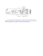
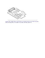
Chapter A Board Diagrams
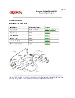
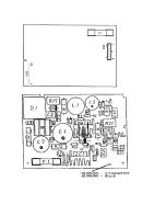
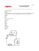
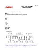
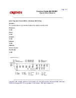
A.2.03 Power Supply (PAII) - Rev A and B
Function
This board converts and regulates the AC voltage input to DC voltage and supplies the DC voltage to the
control board.
Firmware
NONE
Fuses
F1 2.0 amp / 250 VAC
Jumpers
NONE
Sensors
NONE
Switches
NONE
Test Points
CN2: Pin 1 + 40 vdc
CN2: Pin 6 + 5 vdc
CN2: Pin 10 + 8 vdc
Notes
CN1: connection from Transformer
CN2: connection to Power Interconnect Module
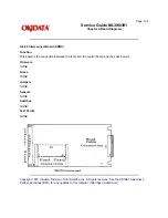
RV-1
This is a variable resistor.
It is used to adjust the space motor drive circuit.
The adjustment is set at the factory.
The power supply board (PAII) was used in both the Microline 390/391 and Microline 320/321 printers.
The adjustment for RV1 is very different for the two series. When installing a replacement power supply
board, verify that RV-1 is properly adjusted for the series printers it is being installed in.
Содержание MICROLINE Turbo ML390
Страница 49: ...Partner Exchange BPX for any updates to this material http bpx okidata com ...
Страница 53: ...Page 29 Service Guide ML390 391 Chapter 2 Principles of Operation ...
Страница 81: ......
Страница 95: ...Partner Exchange BPX for any updates to this material http bpx okidata com ...
Страница 105: ...Copyright 1997 Okidata Division of OKI America Inc All rights reserved See the OKIDATA Business ...
Страница 106: ...Partner Exchange BPX for any updates to this material http bpx okidata com ...
Страница 110: ......
Страница 115: ......
Страница 132: ......
Страница 222: ......


