

Page: 69
Service Guide ML390/391
Chapter 3 Maintenance & Disassembly
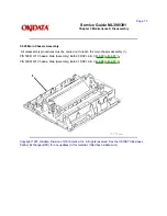
3.2.25 Pressure Roller Assembly
· Perform these procedures:
3.2.01
,3.2.02
, 3.2.04
, 3.2.22
, 3.2.23
.
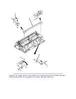
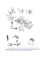
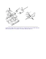
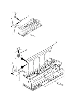
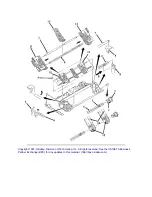
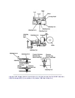
· Remove the paper chute (1).
· Turn the release link (2) as shown in View A so the spine (3) is aligned with the slot (4) in the guide hole.
· Slide the release link off the pressure roller assembly (5).
· Remove the pressure roller assembly by sliding it through the guide hole (6).
NOTES:
Installation
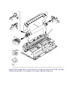
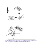
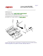
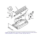
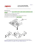
Attach the paper end lever (7) to the shaft of the sensor lever (8). Refer to View B for the correct position.
If the paper end lever is incorrectly positioned, paper jams / no paper-end indications will occur.
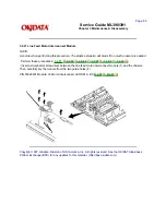
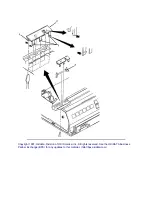
Position the tab of the paper chute firmly with the groove of the main frame.
Engage the cut-sheet paper end lever (attached to the bottom of the paper chute) to the bottom paper end
lever (under the main frame). Then, install the paper chute.
P/N 50061801 Chute: Paper (Assembly) Both 90 RSPL A B C
B.2.05
, B.2.07
P/N 50061901 Chute: Paper (Assembly) Both 91 RSPL A B C
B.2.05
, B.2.07
P/N 50061601 Roller: Pressure (Assembly) Both 90 RSPL A B C
B.2.05
, B.2.07
P/N 50061701 Roller: Pressure (Assembly) Both 91 RSPL A B C
B.2.05
, B.2.07
P/N 53489601 Link: Release All RSPL A B C
B.2.05
, B.2.07
Содержание MICROLINE Turbo ML390
Страница 49: ...Partner Exchange BPX for any updates to this material http bpx okidata com ...
Страница 53: ...Page 29 Service Guide ML390 391 Chapter 2 Principles of Operation ...
Страница 81: ......
Страница 95: ...Partner Exchange BPX for any updates to this material http bpx okidata com ...
Страница 105: ...Copyright 1997 Okidata Division of OKI America Inc All rights reserved See the OKIDATA Business ...
Страница 106: ...Partner Exchange BPX for any updates to this material http bpx okidata com ...
Страница 110: ......
Страница 115: ......
Страница 132: ......
Страница 222: ......