40055101TH Rev.4
440 /
5.
General functional description
5-1
General
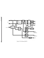
The power supply unit consists mainly of AC transformer and a power PCB (1VP board for
AC120V/2VP board for AC230V). A block diagram of the power supply unit is shown in Figure
A3.6.1 The power PCB is composed of five main circuits: AC input section, heater control
section, low-voltage section, high-voltage section and protection circuit.
The low-voltage section provides a +5V output by a DC-DC converter and other output voltages
(+30V, +8V and -8V) simply by rectifying and smoothing the respective outputs of the AC
transformer. The high-voltage section (TR1, TR2, DB1, DB2, SB1, SB2, CB and CH) produces a
flyback voltage from 5V by using a drum coil and a high-voltage transformer.
5-2
Circuit description
5-2-1 AC input section
1)
AC commercial power is supplied to line filter circuit through the AC inlet, power switch
(SW1) and the fuse (F1). Fuse F1 is used for protecting the heater circuit.
2)
The filter circuit consists of L101,R1, C1, C2, C3 and L1. Capacitors C1 and C2 are not
mounted in the power unit for 120VAC input.
3)
Fuse F2 is used for protection for the double voltage input in the power supply unit for
120VAC input and will not blow by shorting or opening the secondary circuit. This fuse
F2 is not mounted in the power supply unit for 230VAC input.
5-2-2 Heater control circuit
1)
The AC power divided from the AC input section passes through L2 for noise elimination
and is fed to the heater via D1 (operating as a switch) from the power PCB.
2)
The on/off operation of D1 is controlled by the operation of photocoupler PC1 whose
operation is controlled by the HEAT-N signal applied to CN3-B7 pin from the control PCB
(M17 board).
3)
Resistors R2 and R3 connected on the AC side of PC1 are fuse resistors to protect them-
selves from firing when PC1 turns on in the event of D1 open failure.
5-3
Low-voltage section
5-3-1 +30 V circuit
1)
The +30 V circuit pr30 V output by rectifying the corresponding output of
transformer T1 by a rectifier diode DS1 and smoothing the rectified signal by capacitor C7.
2)
Resistor R53 is used to discharge the elecetric charge of C7 when the power switch (SW1)
turned off.
5-3-2 +/- 8 V circuit
1)
The +/- 8 V circuit pr8 V and -8 V outputs by rectifying the corresponding output
of transformer T1 by rectifier diodes D10 and D11 and smoothing the rectified signals by
capacitors C13 and C14.
2)
Resistors R22 and R23 are used to discharge the electric charge of C13 and C14 when the
power switch (SW1) is turned off.
Содержание B4100
Страница 73: ...40055101TH Rev 4 73 2 For OKIFAX 5000 series AC Power Switch AC Inlet FX050VP C2 014...
Страница 158: ...40055101TH Rev 4 158 Appearance of the OKIOFFICE44 OKIFAX 4100 FX048 CP4 1 Fig 01...
Страница 461: ...40055101TH Rev 4 461...
Страница 462: ...40055101TH Rev 4 462...
Страница 463: ...40055101TH Rev 4 463...
Страница 464: ...40055101TH Rev 4 464...
Страница 465: ...40055101TH Rev 4 465...
Страница 466: ...40055101TH Rev 4 466...
Страница 467: ...40055101TH Rev 4 467...
Страница 468: ...40055101TH Rev 4 468...
Страница 469: ...40055101TH Rev 4 469...
Страница 470: ...40055101TH Rev 4 470...
Страница 471: ...40055101TH Rev 4 471...
Страница 472: ...40055101TH Rev 4 472...
Страница 473: ...40055101TH Rev 4 473...
Страница 545: ...40055101TH Rev 4 545 54 SECTION 1 CABINET ASSEMBLY FAX NIP FX048...
Страница 548: ...40055101TH Rev 4 548 SECTION 2 UNIT PRINTER...
Страница 550: ...40055101TH Rev 4 550 SECTION 3 UNIT 048 OPE PANEL...
Страница 552: ...40055101TH Rev 4 552 SECTION 4 OPEPANEL OPERATION PANEL ASSEMBLY...
Страница 554: ...40055101TH Rev 4 554 SECTION 5 FRAME ASSEMBLY SCANNER L...
Страница 556: ...40055101TH Rev 4 556 SECTION 6 PLATE ASSEMBLY SCANNER B...
Страница 558: ...40055101TH Rev 4 558 SECTION 7 PLATE ASSEMBLY SCANNER R...
Страница 560: ...40055101TH Rev 4 560 17 16 15 10 SECTION 8 FRAME ASSEMBLY SCANNER U...
Страница 562: ...40055101TH Rev 4 562 13 SECTION 9 COVER ASSEMBLY TOP...
Страница 564: ...40055101TH Rev 4 564 SECTION 10 PLATE ASSEMBLY BASE...
Страница 569: ...40055101TH Rev 4 569 SECTION 12 PRINTER HEAT ASSY...
Страница 571: ...40055101TH Rev 4 571 SECTION 13 CABLES...
Страница 574: ...40055101TH Rev 4 574 SECTION 1 CABINET ASSEMBLY...
Страница 576: ...40055101TH Rev 4 576 SECTION 2 CONTROL PANEL ASSEMBLY OKIFAX 5200 5300...
Страница 577: ...40055101TH Rev 4 577 SECTION 2 CONTROL PANEL ASSEMBLY OKIFAX 5500 5600...
Страница 579: ...40055101TH Rev 4 579 SECTION 3 PRINTER ASSEMBLY...
Страница 582: ...40055101TH Rev 4 582 SECTION 4 BASE ASSEMBLY 30 37 38...
Страница 585: ...40055101TH Rev 4 585 SECTION 5 SCAN UNIT...
Страница 587: ...40055101TH Rev 4 587 SECTION 6 PAPER GUIDE U ASSEMBLY...
Страница 589: ...40055101TH Rev 4 589 SECTION 7 CABLES 10...
Страница 591: ...40055101TH Rev 4 591 SECTION 8 OPTION TELEPHONE US...
Страница 594: ...40055101TH Rev 4 594 SECTION 8 OPTION TELEPHONE UK ITA NOR DEN BEL...
Страница 597: ...40055101TH Rev 4 597 SECTION 8 OPTION TELEPHONE HOL GER FRA SWITZ AUT INT L...
Страница 615: ...40055101TH Rev 4 615 5 2 PCB Layout TQSB 2PCB PU FG CONTROLLER MOTOR DRIVER SEN2 MOTOR OSC SEN1...
Страница 616: ...40055101TH Rev 4 616 Figure 6 1 6 PARTS LIST SECTION1 CABINET CASSETTE ASSEMBLY 7 2 8 1 6 5 3 4 O P...
Страница 617: ...40055101TH Rev 4 617 SECTION2 MECHANICAL ASSEMBLY Figure 6 2 0 D A E C K B L 9 M F H N G R Q S T U V J I B A B A...


