CHAPTER 3 REPAIR PROCEDURES
3000 Series T32ME & MC Indicators Service Manual
3-7
Ohaus Corporation www.ohaus.com
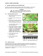
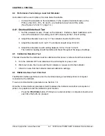
3.4 REPLACING THE PRINTED CIRCUIT BOARD (PCB)
Repairs are not recommended on the PCB. Component parts of the PCB are not stocked by
Ohaus. Replacement is recommended rather than repairing.
Replace the PCB as follows:
1. Unplug the Indicator from the AC power
source.
2. Open the Bottom Housing.
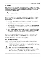
3. Disconnect the wires connected to the
RS232 Connector Block J7.
4. Disconnect the wires from the scale’s
load cell to the PCB’s Load Cell Terminal
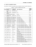
Block J5. (See Figure 3-14, as well as
Figure 3-14. Main PCB.
Figures 3-2 and 3-3.)
5. Carefully disconnect the AC power and battery connectors, and the Membrane Switch
cable.
6. Remove the four screws from the PCB.
7. Lift out the PCB.
CAUTION
When handling the PCB, grasp it by the edges only!
Do not touch the foil side. Static discharge may damage some components.
8. Reconnect the Cable Sets and connectors removed in Steps 3 – 5.
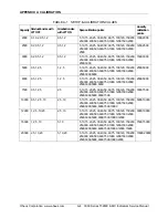
9. Perform calibration procedures. (See Appendix A.)
10.
Perform testing procedures. (See Chapter 4.)
3.5 CABLE
SET
REPLACEMENT
Note
: The cables that connect the PCB to the Load Cell connector, the RS232 connector,
and the power jacks are all sold as a single set. Replace them as follows:
1. Open the Housing.
2.
Disconnect the cables from any of the connectors (RS232, Load Cell, power jacks) for
which the cable set is to be replaced.
3. Reconnect the wires to the PCB.
Содержание T32ME
Страница 2: ......
Страница 4: ......
Страница 8: ...TABLE OF CONTENTS Ohaus Corporation www ohaus com iv 3000 Series T32ME MC Indicators Service Manual...
Страница 22: ...CHAPTER 2 TROUBLESHOOTING Ohaus Corporation www ohaus com 2 4 3000 Series T32ME MC Indicators Service Manual...
Страница 45: ......
Страница 46: ...80253153 P N 80253153 SERVICE MANUAL 3000 SERIES T32MC T32ME INDICATORS...


