PID Control
For various applications the controller can be used as P
control only (set integral = 0, derivative = 0); PI control (set
derivative = 0), PD control (set integral = 0), and PID
control.
Figure 5.4, on page 17, represents the response of a
typical control system using various modes of control.
1.) P control results in a response showing a deviation
(offset), a high overshoot and a moderate period of
oscillation. In addition, a significant length of time is
required before the system ceases to oscillate.
2.) PI control has no offset, but elimination of offset comes
at the expense of higher overshoot, larger period of
oscillation and a longer time required for oscillations to
cease compared with other modes of control.
3.) PD control generally brings the system to steady state
in the shortest time with the least oscillation. However,
it still has offset.
4.) PID control is essentially a compromise between the
advantages of PI and PD control. Offset is eliminated
by the integral action. The derivative action serves to
lower offshoot and to eliminate some of the oscillations
realized with PI control.
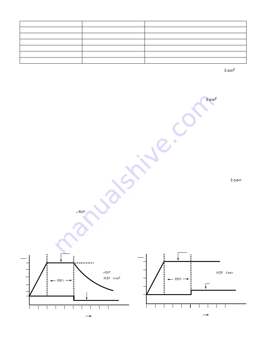
Ramp and Soak Function:
The ETR-3200 can be programmed as a two segment
ramp and soak control. The ramp rate, in degrees per
minute, is determined by the “ “ setting. The soak
function is accomplished by configuring alarm 1 relay as a
timer. The heater (or contactor coil) must be wired in
series through the alarm 1 relay and the “out 1” relay.
Refer to wiring diagram figure 4.8 on page 8. To use this
feature, set A1.SF (alarm 1 special function) to . Set
the soak period at ASP1 (alarm 1 set point). The alarm
relay will be closed at start-up. It will remain closed until
the process temperature has remained at the set point
temperature for the time period (minutes) set in ASP1.
Note the following example: The ramp rate is set to 20
(degrees per minute), A1.SF is set to and ASP1 to
30 (minutes). When the control is powered, the process
will climb at 20 degrees per minute to the set point of
475°F. Once the set point temperature has been reached,
the soak timer begins counting. After a time period of 30
minutes has elapsed, the alarm relay 1 will open and the
process temperature falls at an uncontrolled rate. This
process will repeat every time power has been switched
off and on to the controller. Note diagram 1 below.
Single Event (Dwell) Function:
The single event (dwell) function may be used to control
external devices such as lights, bells or locks. It could
also be used to alert the operator when a guaranteed
soak time has been reached. To use this feature, set
ASP1 (alarm 1 set point) to the time period (in minutes) of
the timer. Set A1.SF (alarm 1 special function) to .
The alarm relay will now operate as a timer. The alarm
relay will be open at start-up. Once the set point tempera-
ture has been reached and the time period set in ASP1
has elapsed, the alarm relay will close. This relay will
remain closed until power to the control has been discon-
nected. The cycle will repeat each time the control has
been energized. Other features such as ramp rate can
also be used. Note diagram 2 below. The set point is
175°F and the dwell time has been set to 30 minutes.
Table 5.6 Tuning Guide
ADJUSTMENT SEQUENCE:
SYMPTOM:
SOLUTION:
1.) Proportional Band
Slow Response
Decrease P Band (Pb)
High Overshoot or Oscillations
Increase P Band (Pb)
2.) Integral Time (Reset)
Slow Response
Increase Reset (i.e. Decrease Integral Time)
Instability or Oscillations
Decrease Reset (i.e. Increase Integral Time)
3.) Derivative Time (Rate)
Slow Response or Oscillations
Decrease Rate (i.e. Decrease Derivative Time)
High Overshoot
Increase Rate (i.e. Increase Derivative Time)
475
400
300
100
75
0
20
40
60
80
90
°
F
30 Minutes
Alarm Relay
OFF
TIME/Minutes
10
30
50
70
ON
Process Value
= 20
=
200
SET POINT = 475
°
F
175
150
125
100
75
0
20
40
60
80
90
°
F
30 Minutes
Alarm Relay
OFF
TIME/Minutes
10
30
50
70
ON
Process Value
Set point
=
Diagram 1: Ramp and Soak
Diagram 2: Single Event


