background image

Officine Gullo

8

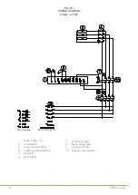
FIG. B/1

WIRING DIAGRAM 

CVS4E - CVS6E

6

549021400M00P00

SCHEMA ELETTRICO – SCHALTPLAN – SCHEMA ELECTRIQUE 

WIRING DIAGRAM – ESQUEMA ELECTRICO 

CPT-74ET , CPT-76ET 

FIG. D 

549026900 M00_00 

230V~50/60Hz 

400V~3N 50/60 Hz 

1

Centralina sicurezza 

acqua 

Wassersicherheitseinheit  Unité de sécurité de l'eau  Water safety unit 

Central de seguridad 

agua 

2

Commutatore Schalter 

Commutateur 

Commutator 

Conmutador 

3

Morsettiera 

alimentazione 

Einspeiseklemme 

Bornier d'alimentation 

Power terminal block 

Tablero de bornes de 

alimentacion 

4

Morsettiera 

commutazione 

Switching 

Klemmenblock 

Bornier de commutation  Switching terminal block  Tablero de bornes de 

conmutación 

5

Resistenze Widerstände  Résistances  Elements 

Resistencias 

6

Sonda di livello 

Pegelsonde 

Sonde de niveau 

Level Probe 

Sonda de nivel 

7

Spia bianca 

Kontrolleuchte weiß 

Lampe témoin blanche 

White pilot light 

Piloto blanco 

8

Spia rossa 

Kontrolleuchte rot  

Lampe témoin rouge 

Red warning light 

Piloto rojo 

9

Spia verde 

Kontrolleuchte grün 

Lampe témoin verte 

Green pilot light 

Piloto verde 

10 

Teleruttore 

Fernschalter  

Téléruptor 

Remote control switch Telerruptor 

1.  Water safety unit

2.  Commutator

3.  Power terminal block 

4.  Switching terminal block

5.  Elements 

6.  Level Probe

7.  White pilot light 

8.  Red warning light

9.  Green pilot light

10.  Remote control switch

9

Officine Gullo

7

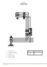
SCHEMA ELETTRICO – SCHALTPLAN – SCHEMA ELECTRIQUE 

WIRING DIAGRAM – ESQUEMA ELECTRICO 

CP-74ET , CP-76ET, CP-78ET 

FIG. E

 549024200 M00_00 


400V~3N 50/60 Hz 

1

Commutatore  Schalter 

Commutateur 

Commutator Conmutador 

2

Morsettiera 

alimentazione 

Einspeiseklemme 

Bornier 

d'alimentation 

Power terminal 

block 

Tablero de bornes de 

alimentacion 

3

Morsettiera 

commutazione 

Switching 

Klemmenblock 

Bornier de 

commutation 

Switching 

terminal block 

Tablero de bornes de 

conmutación 

4

Resistenze  Widerstände 

Résistances  Elements Resistencias 

5

Spia bianca 

Kontrolleuchte weiß 

Lampe témoin 

blanche 

White pilot 

light 

Piloto blanco 

6

Spia verde 

Kontrolleuchte grün 

Lampe témoin verte  Green pilot 

light 

Piloto verde 

7

Termostato 

sicurezza 

Sicherheits-thermostat  Thermostat de 

sécurité 

Safety 

Thermostat 

Termostato seguridad 

1.  Commutator

2.  Power terminal block 

3.  Switching terminal block

4.  Elements 

5.  White pilot light 

6.  Green pilot light

7.  Safety Thermostat

MOD.

JUNCTION BOX

CVCS6E 

CVCS4E

FIG. E 

Fig. B/2

WIRING DIAGRAM 

CVCS4E CVCS6E

Содержание CVS4E

Страница 1: ...INSTRUCTIONS FOR INSTALLATION AND USE CVS4E CVS6E CVCS4E CVCS6E ELECTRIC PASTA COOKER FOR RESIDENTIAL AND PROFESSIONAL USE...

Страница 2: ...le the appliance s maximum power consumption The use of adapters multiple power boards and extension cords is not recommended 8 When not in use switch off the general power supply to the appliance and...

Страница 3: ...CTRICAL DATA TABLE 11 TRANSFORMATION 11 ELECTRIC CONNECTION 11 EQUIPOTENTIAL 12 USER MANUAL STARTING UP 12 INSTRUCTIONS FOR USE 12 TURNING ON 12 EMPTYING THE TUB CVCS E 13 EMPTYING THE TUB CVS4E CVS6E...

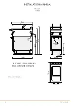
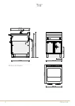
Страница 4: ...UAL FIG A 1 CVS4E 3 cm 4 cm 97 cm 62 cm 70 cm 90 cm 73 cm 67 cm E 70 cm 40 cm 20 cm 40 cm 40 cm E Su richiesta scarico posteriore Drain on the wall on request E LEGEND Electric connection Connessione...

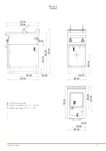
Страница 5: ...Officine Gullo E Electrical connection F Water connection ISO 7 1 3 4 M S Water drainage ISO 7 1 1 M FIG A 2 CVCS4E E Electrical connection F Water connection ISO 7 1 3 4 M S Water drainage ISO 7 1 1...

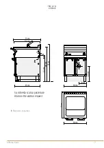
Страница 6: ...70 cm 20 cm 60 cm 40 cm E 3 cm 4 cm 97 cm 62 cm 70 cm 90 cm 73 cm 67 cm E Su richiesta scarico posteriore Drain on the wall on request E LEGEND Electric connection Connessione Elettrica FIG A 3 CVS6E...

Страница 7: ...0 cm 20 cm 60 cm 40 cm E 3 cm 4 cm 97 cm 62 cm 70 cm 90 cm 73 cm 67 cm E Su richiesta scarico posteriore Drain on the wall on request E LEGEND Electric connection Connessione Elettrica E Electrical co...

Страница 8: ...witching Klemmenblock Bornier de commutation Switching terminal block Tablero de bornes de conmutaci n 5 Resistenze Widerst nde R sistances Elements Resistencias 6 Sonda di livello Pegelsonde Sonde de...

Страница 9: ...tation Switching terminal block Tablero de bornes de conmutaci n 4 Resistenze Widerst nde R sistances Elements Resistencias 5 Spia bianca Kontrolleuchte wei Lampe t moin blanche White pilot light Pilo...

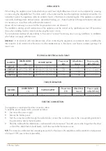
Страница 10: ...ERISTICS The system must be connected to a drinking water supply with the following characteristics Failure to do so automatically invalidates the guarantee Total hardness 0 5 to 5 F to prevent the bu...

Страница 11: ...l contacts from the mains must be installed above it this device must have a contacts opening of at least 3 mm TECHNICAL ELECTRICAL DATA TABLE MODELS DIMENSIONS cm POWER SUPPLY Power max kW Absorbitio...

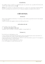
Страница 12: ...care Check the connection of the appliance and start it up following the instructions INSTRUCTIONS FOR USE Use the appliance only under surveillance Never start up the appliance without water With pas...

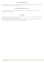
Страница 13: ...the safety device A upwards and move lever B to open the outlet tap Once emptied the tub close the outlet tap ANOMALIES If the probe does not detect the presence of water in the tank for more than 15...

Страница 14: ...uld then be dried Do not use polish as this is suitable for maintaining the gloss but not the antique finish and could result in an effect that is not compliant with our products Any spots that may ap...

Страница 15: ...the after sales service PROCEDURE TO FOLLOW IF THE APPLIANCE IS NOT GOING TO BE USED FOR SOME TIME Turn off the appliance disconnect the power supply and clean the appliance as specified above MAINTE...

Страница 16: ...Tel 39 055 656 0324 info officinegullo com Via Della Torricella 29 Antella Bagno a Ripoli 50012 Florence Italy OFFICINEGULLO COM en international V 2 3 9 18...

Отзывы: