background image

22 


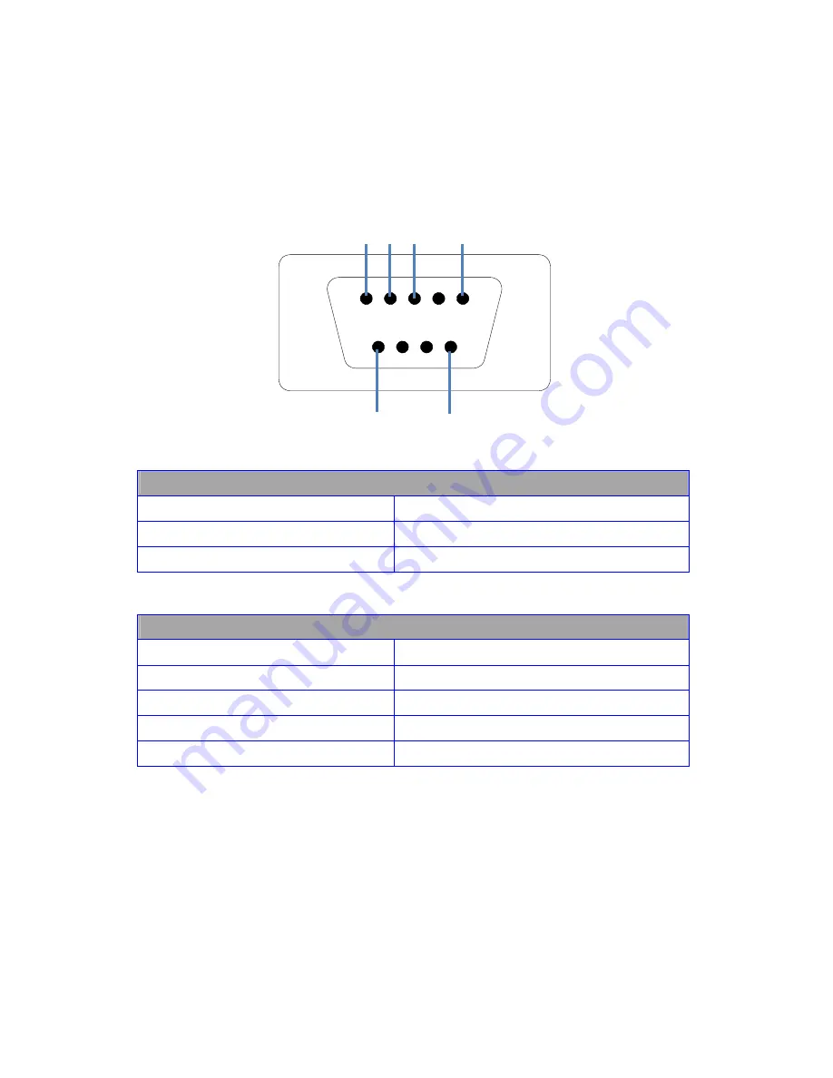
Serial Control RS-232 Control Setup: 

The Matrix can be easily integrated with 3

rd

 Party control systems via 

RS232 control. The following shows the RS-232 pin out and control 
protocol for controlling the Matrix. 


RS-232 Port 

Pin 2 

Receive Data 

Pin 3 

Transmit Data 

Pin 5 

Signal Ground 


Serial Port Setting 

Baud Rate 

9600 

Data Bits 

Parity Check 

none 

Stop Bits 

Flow control 

none 


1

6

2 3

Содержание HD4XSTPMX

Страница 1: ...1 Installation Guide Model HD4XSTPMX PRO HD HOME THEATER SERIES ...

Страница 2: ...ation 11 IR Installation 13 EDID Configuration 14 Changing EDID mode 15 Scene Select 16 Scene Programming 17 Powering modes 18 Sleep mode 19 USB Service Port 20 Serial Control 21 Serial Control RS 232 Control Setup 22 Serial Control Via LAN Port Control Setup 23 Serial Commands Basic 28 Serial Commands switching 29 Serial Commands Status Response code 31 Serial Commands Forwarding 32 Zone Receiver...

Страница 3: ... 60m Power over Ethernet provides power to Zone Receivers IR and RS 232 over the same CAT6 cable IR from remote Zones to control the Matrix 4x Sources Routed and your AVR RS 232 command forwarding to each Zone over CAT6 EDID Management plus custom EDID via USB service port Front panel control for Scene setting selection with full lock out Discrete IR codes for simple system integration Wired IR po...

Страница 4: ...verview Item Description 1 Output Select Press to switch inputs for output Zones 2 LED Display 3 IR Receiver IR receiver 4 Control and function select 1 Output Select 2 Led Display 3 IR Receiver 4 Control and function select ...

Страница 5: ...to prevent accidental switching When front panel button locked pressing front panel buttons will be ignored O U T A B C D E F G H I N 1 1 1 1 1 1 1 1 L O C K Press fn lock unlock Unlock front panel buttons Unlocks the front panel buttons O U T A B C D E F G H I N 1 1 1 1 1 1 1 1 Press fn lock unlock Home Menu O U T A B C D E F G H I N 1 1 1 1 1 1 1 1 Press Home Firmware EDID Sleep Mode setting F i...

Страница 6: ... HDMI cables to Source device 11 HDMI Output A Note 1 connect High Speed HDMI cables to AVR or Display device 12 Optical Audio Output Note 1 Outputs audio over Toslink Audio will play the Out A source selection 13 Analog 2ch Audio Note 1 Outputs audio over 2ch Audio will play the Out A source selection 14 CAT6 Output A H connect Twisted Pair cables to Octava Zone Receiver Rx unit 15 USB Port for c...

Страница 7: ... Connect to HD4xSTPMX with CAT6 ZR 2 HDMI Out to display Connect to HDTV using High Speed HDMI cable ZR 3 Power Data Indicator indicates Zone Receiver is receiving power and linked with the matrix unit ZR 4 IR RX receive connect Octava supplied IR Receiver cable ZR 5 IR TX transmit Optional Connect with an Octava IR emitter if IR control of TV is needed For example your control system controls you...

Страница 8: ...adcast for maximum utility Routed IR The IR Out 1 4 are routed for optimum IR control For example If Zone H is switched to HDMI Input 4 IR Commands from Zone H will only be sent to control Input 4 and not affect other input sources IR Broadcast The IR Broadcast port routes All IR received to the IR Broadcast port IR Receiver IR 1 IR Receiver cable IR 2 IR Emitter IR Emitter ...

Страница 9: ... of Matrix or 2 Zone Receiver Refer to page 18 for more details Standby OFF Remote Command received by Result Matrix Matrix Standby low power mode CAT6 Output A H OFF Zone Receivers OFF Zone Receiver Matrix Standby low power mode CAT6 Output A H ON Zone Receivers ON Turn On Matrix Zone Control Example Press C3 switches Output C to Input3 Standby Off Master Remote Type D Reserved for Customization ...

Страница 10: ...B standard when terminating your LAN cables Ethernet cable installation recommendations Use your cable suppliers recommended RJ 45 connector crimp tool with your CAT5 CAT6 cables and ensure you pay particular attention to the quality of the termination on all cables DO Recommend Use shielded CAT6a with good RJ 45 terminators Use a direct cable connection between the Matrix and Receiver unit DO NOT...

Страница 11: ...o Sources Power OFF Matrix 2 Connect the 48VDC power supply to matrix 3 Connect the 9VDC power supply to matrix 4 Verify that the Matrix is turned on Welcome screen as shown is displayed O C T A V A 5 Verify that the LED indicators on the CAT6 outputs of the Matrix are ON 6 Please read the Ethernet cable recommendations cabling recommendations on page 10 before proceeding Continued on next page ...

Страница 12: ...isplay 9 Repeat step 7 and 8 for all Zones Connecting HDMI sources outputs and Audio Output 10 Turn OFF the Power to the Matrix with remote 11 Connect HDMI sources to HDMI IN 1 4 12 Connect HDMI Output A to display or receiver with HDMI cable optional 13 Connect Audio outputs to Audio system optional Note 1 HDMI Output Toslink and Analog 2ch output all mirror Zone A Reset System 14 Turn ON the mat...

Страница 13: ...RX as shown 2 Insert IR Emitter cable to the IR Out ports of the Matrix HD70STPMX as shown Connect a IR emitter cable to the IR Broadcast port if you need this feature 3 Remove the double sided tape on the IR Emitter 4 Locate the IR receiver on the video source Place the Emitter head over the source IR receiver ...

Страница 14: ... Audio Description A 480P 720 i P 1080 i P 2 CH PCM Internal EDID B 480P 720 i P 1080 i P 2 CH PCM Bitstream Dolby Digital DTS Internal EDID C 480P 720 i P 1080 i P 3D specifier 2 Ch PCM Bitstream Dolby Digital DTS Internal EDID D 480P 720 i P 1080 i P 3D specifier 2 Ch PCM Bitstream Dolby Digital DTS Dolby Tru HD DTS Master Audio Internal EDID E 480P 720i P 1080 i 2 CH PCM Internal EDID OR Custom...

Страница 15: ...U T A B C D E F G H I N 1 1 1 1 1 1 1 1 2 Press Menu Button Goto EDID Menu Reference Page 14 for EDID Modes E D I D S e l e c t P r e s s A B C D o r E 3 Select EDID A B C D or E Press Cancel to exit to previous screen E D I D A V i d 4 8 0 1 0 8 0 P A u d 2 c h P C M E n t e r Example EDID A shown 4 Press Enter to load Press Cancel to exit to previous screen L o a d A P r e s s E N T E R t o S T ...

Страница 16: ...rations A All outputs connected to Input 1 P r o g r a m O u t A B C D E F G H S c e n e A I n 1 1 1 1 1 1 1 1 B All outputs connected to Input 2 P r o g r a m O u t A B C D E F G H S c e n e B I n 2 2 2 2 2 2 2 2 C All outputs connected to Input 3 P r o g r a m O u t A B C D E F G H S c e n e C I n 3 3 3 3 3 3 3 3 D All outputs connected to Input 4 P r o g r a m O u t A B C D E F G H S c e n e D ...

Страница 17: ...1 1 1 1 1 E n t e r Example Scene A shown 4 Press Menu to enter program mode Press Cancel to exit to previous screen P r o g r a m O u t A B C D E F G H S c e n e A I n 1 1 1 1 1 1 1 1 5 Use the Octava Remote control or front panel buttons A H to program the Scene for your preference Example Programming Scene A Out A E 1 Out B F 2 Out C G 3 Out D H 4 P r o g r a m O u t A B C D E F G H S c e n e A...

Страница 18: ...OFF Zone Receivers OFF Note 2 When matrix is in Standby or OFF mode the Fan will continue to run for approximately 3 minutes then the Fan will shut off The following shows how to set the matrix to ON Standby Off Mode Front Panel Buttons IR Remote RS 232 ON Send IR command Send Turn ON Power command Standby NA Send IR command to matrix via Zone Receiver OFF Send IR command to matrix via front panel...

Страница 19: ...he instructions below Action Display 1 Press Menu Button Goto Sleep Menu S l e e p M o d e E n t e r 2 Press Enter Press Cancel to exit to previous screen S l e e p M o d e O N P r e s s A S l e e p M o d e O F F P r e s s H 3 Press A for Sleep Mode ON Press H for Sleep Mode OFF S l e e p M o d e O N P r e s s A S l e e p M o d e O F F P r e s s H To view if Sleep Mode is on or off press the MENU ...

Страница 20: ...20 USB Service Port The USB port is for service EDID updates or customization requests Contact us for this feature or visit out support page for more info www octavainc com support and updates html ...

Страница 21: ...ll be via RS 232 Port 2 Select A to control matrix via RS 232 port Select E to control matrix via LAN Control Port R S 2 3 2 D B 9 P r e s s A L A N R J 4 5 P r e s s E Display Indicates Serial Control will be via RS 232 Port RS 232 Control O U T A B C D E F G H I N 1 1 1 1 1 1 1 1 Indicates Serial Control will be via RS 232 Port Indicates Serial Control will be via LAN Port LAN Port O U T A B C D...

Страница 22: ...trol systems via RS232 control The following shows the RS 232 pin out and control protocol for controlling the Matrix RS 232 Port Pin 2 Receive Data Pin 3 Transmit Data Pin 5 Signal Ground Serial Port Setting Baud Rate 9600 Data Bits 8 Parity Check none Stop Bits 1 Flow control none 1 5 6 9 2 3 ...

Страница 23: ...TPMX Complete detail instructions on using the NE 4100 can be found here http www moxa com doc manual NE 4100 v6 NE 4100_Series_Use rs_Manual_v6 pdf To Use the LAN port for serial control you may follow these instructions Step Serial Control Via LAN Port 1 Connect Ethernet cable to the LAN Port of the Matrix and your LAN 2 Set Matrix to LAN serial port control See page 21 3 Download and Install NP...

Страница 24: ...24 Step Serial Control Via LAN Port 5 Click ADD 6 Click Search Continued on next page ...

Страница 25: ...Via LAN Port 7 Wait for Search to complete Make sure a device is found If not repeat step 1 6 8 Click OK 9 Click Yes on the notification Wait until activation is complete 10 Click OK on the notification Continued on next page ...

Страница 26: ...dress Assigned as shown on your program screen 12 Write down the COM Port Write down the IP Address 13 Open Local Area Connection Properties Double click on Internet Protocol Version 4 TCP IPv4 Continued on next page assigned Com Port IP address of Moxa Serial server ...

Страница 27: ...me unused number for the 4th octet Key in 255 255 255 0 for Subnet mask Click OK Done Use your Control Program and select the COM Port Assigned by Nport Driver Manger to control the Matrix Serial commands are on page 28 see step 11 Enter 199 or an unused octet Can not be same as the last octet of the IP address assigned to the Moxa serial server shown in Step 11 ...

Страница 28: ...Status 0x02 0x30 0x30 0x31 0x03 Turn ON LCD 0x02 0x30 0x30 0x33 0x03 Turn OFF LCD 0x02 0x30 0x30 0x34 0x03 Turn ON Power 0x02 0x30 0x30 0x35 0x03 Turn OFF Power 0x02 0x30 0x30 0x36 0x03 Standby 0x02 0x30 0x30 0x43 0x03 Sleep Mode ON 0x02 0x30 0x30 0x41 0x03 Sleep Mode OFF 0x02 0x30 0x30 0x42 0x03 Example To turn off LED send Command 0230303403 in Hex Note The commands are in HEX No spaces between ...

Страница 29: ...x33 0x31 0x03 Switch OUT C to Input port 2 0x02 0x32 0x33 0x32 0x03 Switch OUT C to Input port 3 0x02 0x32 0x33 0x33 0x03 Switch OUT C to Input port 4 0x02 0x32 0x33 0x34 0x03 Output D Switching Commands Switch OUT D to Input port 1 0x02 0x32 0x34 0x31 0x03 Switch OUT D to Input port 2 0x02 0x32 0x34 0x32 0x03 Switch OUT D to Input port 3 0x02 0x32 0x34 0x33 0x03 Switch OUT D to Input port 4 0x02 ...

Страница 30: ...Switch OUT H to Input port 3 0x02 0x32 0x38 0x33 0x03 Select OUT H to Input port 4 0x02 0x32 0x38 0x34 0x03 Select ALL Output Switching Commands Switch ALL Outputs A H to Input port 1 0x02 0x32 0x39 0x31 0x03 Switch ALL Outputs A H to Input port 2 0x02 0x32 0x39 0x32 0x03 Switch ALL Outputs A H to Input port 3 0x02 0x32 0x39 0x33 0x03 Switch ALL Outputs A H to Input port 4 0x02 0x32 0x39 0x34 0x03...

Страница 31: ...n1 2 3 or 4 Byte 8 OUTPUT G connected to In1 2 3 or 4 Byte 9 OUTPUT H connected to In1 2 3 or 4 1 2 3 or 4 input selected Byte 10 HDMI Input 1 is connected and detected Byte 11 HDMI Input 2 is connected and detected Byte 12 HDMI Input 3 is connected and detected Byte 13 HDMI Input 4 is connected and detected 0 input NOT detected 1 input detected N not applicable Byte 14 LCD backlight on or off 0 L...

Страница 32: ...xA6 G 0x37 7 0xA7 H 0x38 8 0xA8 9 0xA9 10 0x10 11 0x11 12 0x12 99 0x99 Example To send a 9600 baud 10 byte command to Zone H Step1 Send RS 232 Forwarding Command to matrix This will set up the matrix to forward the next 10 Byte command to Zone H at 9600baud STX Data Rate Zone of bytes ETX 9600 Bps Zone H 10 bytes 0x02 0x41 0x38 0x10 0x03 Step 2 Send the 10 byte commands that you wish to pass to Zo...

Страница 33: ...the attached display A 3 pin Phoenix connector is provided to connect with a RS 232 serial cable Prepare your serial cable according to diagram below The following shows the cable configuration for sending serial commands from the Matrix to the RX display side Sending Serial Commands from Matrix unit to RX Unit Serial Port cable RX side ...

Страница 34: ... additional cards Procedure 1 Disconnect 48VDC and 9VDC power supply from the Matrix 2 Disconnect ALL cables from the matrix 3 Remove the TX card thumb screws 4 Remove cover screws x13 with screw driver 5 Remove cover Continued on next page Step1 Step 2 remove all cables from matrix Step 3 Step 4 Step 5 ...

Страница 35: ...ish to add Out E shown 7 Install the TX card to the slot 8 Install top cover back on matrix 9 Tighten TX card thumb screws 10 Install the cover Screws x13 with Philips screw driver 11 Done Goto page 11 for instruction on installing the matrix Step 6 Step 7 Step 8 Step 9 Step 10 ...

Страница 36: ... OR TORT INCLUDING WITHOUT LIMITATION NEGLIGENCE AND STRICT LIABILITY OR OTHERWISE IN NO EVENT SHALL OCTAVA INC OR ITS SUPPLIERS BE LIABLE FOR ANY SPECIAL INCIDENTAL CONSEQUENTIAL OR OTHER INDIRECT DAMAGES INCLUDING WITHOUT LIMITATION LOSS OF REVENUES PROFITS OR OPPORTUNITIES HOWEVER CAUSED ON ANY THEORY OF LIABILITY WHETHER OR NOT OCTAVA INC HAS BEEN ADVISED OF THE POSSIBILITY OF SUCH DAMAGES WHI...

Страница 37: ...ity using Octava supplied IR cables RS 232 Control the Matrix using serial commands or 3 rd party control software HEX commands available Serial Commands can also be routed to the connected Zone receivers via your CAT6 cables to control your HD Displays USB USB port provided Firmware updates customization and for service LAN IP Port LAN port provided for Firmware updates customization and control ...

Отзывы: