8
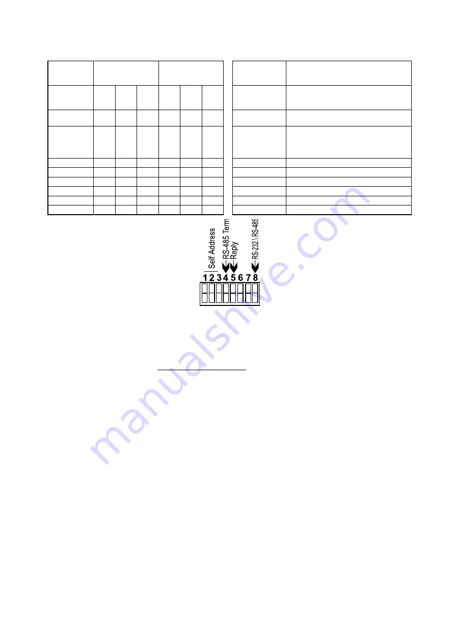
Table 3: DIP Switches Configuration
MACHINE
NUMBER
SELF ADDRESS
DIP SWITCH
DIP switch #4
"ON"=
Connects the termination resistor.
"OFF"=
Disconnects the termination
resistor.
2
1
0
3
2
1
DIP switch #5
"ON"=
Enables reply from switcher to PC.
"OFF"=
Disables reply from switcher to
PC.
1. (Master)
0
0
0
ON
ON
ON
DIP
switch #6,
DIP switch #7
Not used
2.
0
0
1
ON
ON
OFF
DIP switch #8
"ON"=
Enables RS-232 communication
between switcher and PC.
"OFF"=
Enables RS-485 communication
between switcher and PC.
3.
0
1
0
ON
OFF
ON
4.
0
1
1
ON
OFF
OFF
5.
1
0
0
OFF
ON
ON
6.
1
0
1
OFF
ON
OFF
7.
1
1
0
OFF
OFF
ON
8.
1
1
1
OFF
OFF
OFF
Figure 3: DIP switches General View
RS-232 and RS-485 Operation
Connections made between your switcher and a PC are accomplished using your computer’s RS-232
communication port, or by connecting the PC to the RS-485 terminal block connector. Bear in mind
that serial communication between Matrix Switchers is always via RS-485. The RS-232 port is either
a DB-9 (9-pin port) or DB-25 (25-pin port). The cable connecting your switcher to the PC should be
wired as shown in Figure 4. A 9-25 pin adapter or 9-9 pin null-modem adapter is included for your
convenience. The null-modem adapter is wired as shown in Figure 4. If using the adapter
(recommended), plug it into the PC’s serial port, and connect via a flat-cable from the other end of the
adapter to your switcher. Keep in mind that it is not recommended to extend an RS-232 signal beyond
a length of 30 feet, without the use of an RS-232 to RS-422 converter at both the PC and the switcher.
If five machines and a PC are cascaded together for example, using RS-485 interconnection,
disconnect the termination resistors on all machines except the fifth (see Figure 6). For similar setup,
without a PC connected on the RS-485 line, disconnect all resistors except for the first and fifth
machines.
Содержание OMX-SW6x6
Страница 1: ...OMX SW6x6...


