3
www.observint.com
© 2019 Observint Technologies. All rights reserved.
Step 3. Select the video format
You can set the video format of the camera to either TVI, AHD, CVI, or CVBS. The video format currently
selected usually appears in the upper left corner of the Live View screen. The format you select must be
compatible with your DVR or monitoring device. To change the format to another option:
1.
Find the tag on the video drop cable for the latest instructions.
2.
Unscrew the cap on the button switch. See the drop cable photo on page 1.
3.
Press and hold switch button for 5 seconds to change the video format to the next format in the
rotation shown on the tag. Repeat this step until the format you prefer appears on the Live View
screen.
4.
Screw the cap back onto the button switch drop cable. Ensure that the cap is tight.
5.
If installing the camera onto a junction box, secure the junction box front plate with the camera to
the junction box.
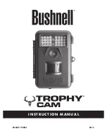
Step 4. Adjust camera pan, tilt and rotation
Adjust the camera pan, tilt and rotation to point the camera at your surveillance target. When pointing the
camera, observe the
Live View
display on a recorder or remote login.
Camera adjustments
1.
Loosen the pan lock nut and the tilt lock screw.
Pan lock nut
Pan adjustment: 0° ~ 360°
Tilt
adjustment
0° ~ 180°
Tilt lock screw
Rotation lock screw
2.
While observing video from the camera, point the camera at the center of your surveillance target.
3.
Tighten the pan lock nut and tilt lock screw.
4.
Rotation adjustment
: If necessary, loosen the rotation lock screw, and then rotate the camera
body to produce a good horizontal alignment of the image. The rotation adjustment range is
0° ~ 360°
.
Tighten the rotation lock screw.
Step 5. Open the OSD menu
The On Screen Display (OSD) provides configuration options for refining the performance of the camera. It
also can be used to block sensitive portions in the field of view (Privacy).
You can open the OSD menu system from the recorder Live View display.
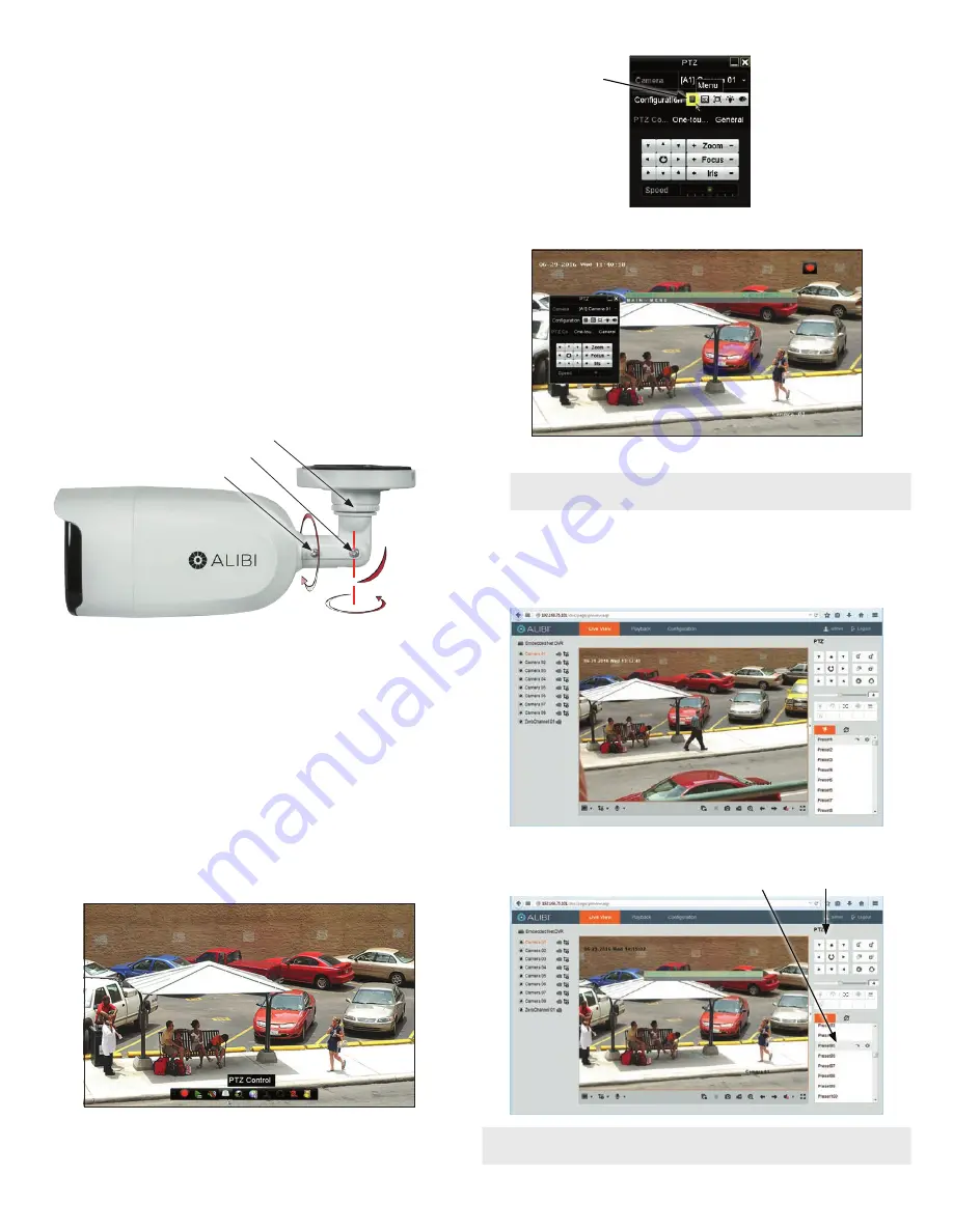
1.
Open the recorder Live View screen, and then click inside the screen where the PTZ camera video
image is displayed. See below.
a.
Click the
PTZ Control
icon in the Quick Setting Toolbar. The PTZ camera Live View window
will expand to full screen and the pop-up window shown below will open.
Menu
icon
b.
In the
PTZ Control
panel pop-up window, click the
Menu
icon on the
Configuration
line.
c.
Drag the PTZ Control window to a position where it doesn’t cover the OSD menu
NOTE
The PTZ Control window direction buttons and the
Iris +
and
Iris
-
keys are used to
navigate the OSD menu and set configuration options in the camera. See .
•
Opening the OSD Menu through remote login to the recorder
To open the OSD menu during a remote login to the recorder:
a.
After logging into the recorder, open the camera in a single Live View window.
b.
In the PTZ control panel, scroll down the Preset list to
Preset95
, click the entry to highlight
it, and then click the
Call
icon. See below. The OSD
MAIN MENU
screen will open.
PTZ control panel
Preset95
Call
icon
NOTE
The PTZ control panel direction buttons and the
Iris +
and
Iris -
keys are used to navigate the OSD
menu and set configuration options in the camera.