DE
EN
FR
NL
ES
PT
IT
DA
NO
SV
FI
HU
PL
CS
SK
SL
HR
RO
BG
UK
RU
CN
15
•
Route cables/hoses such that they are
protected from damage and do not pre-
sent a tripping hazard.
•
Only open the unit housing or its at-
tendant components, when this is ex-
plicitly required in the operating instruc-
tions.
•
Only carry out work on the unit that is
described in this manual. If problems
cannot be overcome, please contact an
authorised customer service point or,
when in doubt, the manufacturer.
•
Only use original spare parts and acces-
sories for the unit.
•
Never carry out technical modifications
to the unit.
INSTALLATION AND CONNECTION
N O T E
For permanent installation of the pump,
use flexible compression-proof hoses to
connect it to the pipe network to reduce
the noise of the pump.
N O T E
If the pump is used as a booster pump,
ensure that the max. internal pressure of
6 bar on the pressure side is not ex-
ceeded.
•
The pump pressure is added to the pre-
pressure.
•
Example: Pre-pressure = 1 bar, max.
pressure of the pump = 4.5 bar, total
pressure = 5.5 bar.
•
Install the pump in a horizontal and sta-
ble position in a dry place.
– For permanent installation of the
pump, ensure that a sufficiently large
collecting basin can be positioned un-
derneath the discharge screw for
emptying the pump.
•
If possible, install the pump in a higher
position than the container/reservoir
from which the water is to be pumped. If
this is not possible, a pressure-proof
valve must be fitted between the pump
and the suction hose.
•
Only use vacuum-proof pressure hoses
on the pressure and suction side.
N O T E
OASE recommends: Additionally fasten
the suction hose (e.g. by tying it to a
wooden stake) to relieve the weight of
the hose on the pump.
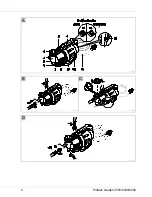
B
•
Screw a suction and pressure hose with
25.0 mm internal diameter (1") onto the
connections.
OPERATION
W A R N I N G
Risk of injury due to hot water!
Burns to parts of the body.
•
Water remaining in the pump may be
heated to a high temperature in the
event of defective electronics or lack of
water supply on the suction side.
•
Isolate the unit (disconnect from the
power supply) before carrying out any
work on it.
•
Disconnect the pump from the mains at
the main circuit breaker or pull the
power plug, and allow the water to cool
down.
Start-up of the device
It is necessary to fill the pump and expel
the air from the suction line before using it
for the first time. It can take several
minutes to expel air from the suction line.
How to proceed:
C
1. Unscrew the filter cover. A screwdriver
can be inserted from the side into the re-
cesses of the cover to aid unscrewing.
2. Open the shut-off device in the pressure
line.
Содержание ProMax Garden 3500
Страница 1: ...ProMax Garden 3500 5000 6000 5 ...
Страница 2: ...2 ProMax Garden 3500 5000 6000 A POX0025 B C POX0026 POX0027 D POX0043 ...
Страница 3: ... 3 E POX0028 ...
Страница 200: ...200 ProMax Garden 3500 5000 6000 POX0035 ...
Страница 201: ...43920 08 16 ...


