


UM10468
All information provided in this document is subject to legal disclaimers.
© NXP B.V. 2011. All rights reserved.
User manual
Rev. 1 — 30 August 2011
12 of 27
NXP Semiconductors
UM10468
SSL2108X buck evaluation board
6. Functional
description
The SSL2108X IC (
) uses Boundary Conduction Mode (BCM) with peak current
control. The SSL2108X controls and drives the converter. In addition, the SSL2108X
offers a low component count LED buck converter solution. Valley switching and PWM
dimming are implemented into the SSL2108X together with several protection features:
•
UnderVoltage LockOut (UVLO)
•
Leading-Edge Blanking (LEB)
•
OverCurrent Protection (OCP)
•
Internal OverTemperature Protection (OTP)
•
Brownout protection
•
Short-Winding Protection (SWP)
•
Output Short Protection (OSP)
•
NTC over temperature control and protection
Both the SWP and the OSP are latched protections circuits. These protective features
cause the IC to halt until a reset is executed. If V
CC
drops below its restart level, the IC
resets the latched protection mode. Restarting the evaluation board is done by removing
AC mains supply voltage. All other protective features cause a safe restart of the
converter. Refer to the
SSL2108X data sheet
for detailed information on all protective
features.
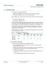
Depending on the selected SSL2108X version, the evaluation board is optimized for an
LED voltage, LED current and resulting output power. See
. As a default, jumper
J7A is set to apply the full output power to the LED load. Setting jumper J8A or J9A
instead reduces the output power to either 66 % or 33 % of the original output power.
Remark:
Do not remove or set jumpers when the board is connected to the AC mains
supply voltage because LED damage can occur.
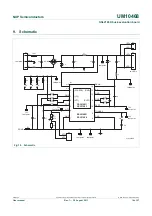
Fig 11. Board connection diagram
J5
K3
LED +
LED load
LED load
LED -
LED +
LED -
K2
IC1
X55
J6
J10
D2
C1
D1
C8
L2
FUSE 1
K1
K4
RT1
C2
D3
L3
C3
L1
J3
J2
J1
J4
J9
J8
J7
NTC -
L
N
NTC +
mains
input
external NTC/
PWM input
019aac358