


S32R274 EVB User Guide
10
Jumper
Label
Description
J35
CAN
1-2: 5.0V_SR to PHY U1 V
CC
3-4: 12V to PHY U1 V
BAT
J37
CAN
PHY U1 TX to MCU
1-2: TTCAN TX
2-3: MCAN1 TX
J38
-
PHY U1 RX to MCU
1-2: TTCAN RX
2-3: MCAN1 RX
J36
-
PHY U1 signal out
1: ERR
2: INH
3.3
RS232 Configuration
Female DB9 connector J19 and MAX3221E RS232 transceiver device provide a physical RS232
interface, allowing a direct RS232 connection to a PC or terminal.
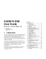
The pin-out of these connectors is detailed in Figure 7. Note that hardware flow control is not supported
on this implementation.
Figure 7.
Figure 7.
RS232 physical interface connector
On default the RS232 interface is not enabled. To enable the RS232 interface the user needs to place the
jumpers detailed in Table 4
.
Table 4.
RS232 control jumpers
Jumper
Label
Description
J13
SCI TX
TX enable
J14
SCI RX
RX enable
J25
SCI_PWR
Transceiver power on