


NXP Semiconductors
S32K312EVB-Q172 HWUM
S32K312EVB-Q172 | S32K312EVBQ172ND - Hardware User Manual
S32K312EVB-Q172
S32K312EVBQ172ND
HWUM
All Information provided in this document is subject to legal disclaimers
© NXP B.V. 2020. All rights reserved
NXP Semiconductors
REV A1
– 01/2022
Page
15
of
25
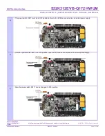
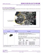
8.2 On-board Debugger
The EVB incorporates an On-Board Debugger embedded well as JTAG connectors. It bridges serial and debug communications between
a USB host and an embedded target processor.
Figure 11. S32K312EVB-Q172
– On-board S32K3 Debugger
Table 7. Programming and Debug Connectors
Connector
Reference/
Component
Description
20-Pin Cortex
Debug + ETM
Connector
J50
This small 20-pin (0.05") connector provides access to SWD, SWV, JTAG, and ETM
(4-bit) signals available on a Cortex-M3/M4/M7 device.
A 20-pin header (Samtec FTSH-110-01) is specified with dimensions:
0.50" x 0.188" (12.70 mm x 4.78 mm).
NOTE - JTAG
– TRACE Signals
Due that the MCU ports used for the trace signals also are shared with other
interfaces. It is important to isolate these signals/interfaces for the
J4-Cortex Debug
D ETM connector
.
SIGNAL
Name
MCU
Port
Name
Signal
Resistor
COMMENT
TRACE_CLK
PTC2
R192
Disabled as DEFAULT
TRACE_D0
PTD7
R452
Disabled as DEFAULT
TRACE_D1
PTD12
R190
Disabled as DEFAULT
TRACE_D2
PTD11
R435
Disabled as DEFAULT
TRACE_D3
PTD10
R511
Disabled as DEFAULT
All TRACE signals are DISABLED as default configuration. In order to enable the TRACE interface, the MCU signals routed to the QSPIA interface
must be disabled and isolated.