NXP Semiconductors QN9080-001-M17 DK Скачать руководство пользователя страница 20


NXP Semiconductors 

UM11184 


QN9080-001-M17 

DK User’s Guide 

UM11184 

All information provided in this document is subject to legal disclaimers. 

© NXP B.V. 2019. All rights reserved. 

User Manual 

Rev. 0 

— January 2019 

20 of 27 


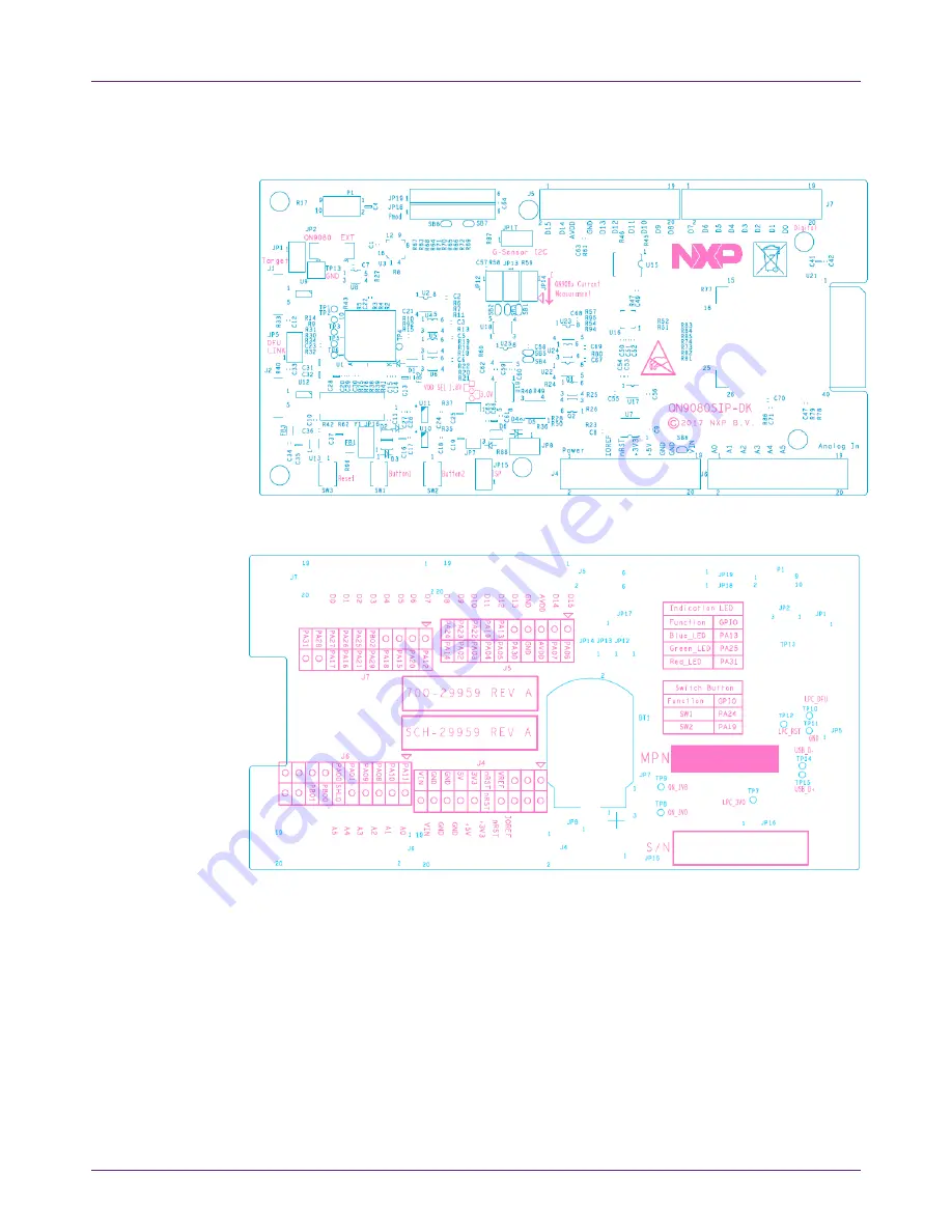
Fig 29.  Top silkscreen 


Fig 30.  Bottom silkscreen 

Содержание QN9080-001-M17 DK

Страница 1: ...N9080 001 M17 DK User s Guide Rev 0 January 2019 UM11184 Document information Info Content Keywords QN9080 001 M17 DK QN9080 001 M17 BLE Abstract This document is an introduction to the QN9080 001 M17...

Страница 2: ...signed to ease the evaluation of the chip s functions and performance on customer side to make it easy to control connect and debug the extension hardware and make it easy for the customer to develop...

Страница 3: ...1 Hardware overview The QN9080 001 M17 DK board is shown in Fig 1 The detailed information is listed in Table 1 Fig 1 Board overview Table 1 QN9080 001 M17 DK board s mark information list Number Name...

Страница 4: ...ader J4 and J6 QN9080 001 M17 GPIO for testing and compatible with the Arduino interface 12 Jumper JP12 JP13 JP14 These jumpers are used for the power consumption test 13 Header J8 PMod interface conn...

Страница 5: ...ed I2C path enabled JP16 Pin 1 2 shorted When the DK board is powered by a battery leave it open J1 on module board Pin 1 2 shorted Internal NTAG powered on J2 on module board Pin 1 2 shorted When the...

Страница 6: ...a high performance MCU 32 bit Arm Cortex M4F on chip memory and peripherals for users to develop a truly single chip wireless MCU solution Fig 4 Module board details Table 3 QN9080 001 M17 module boa...

Страница 7: ...7 of 27 The QN9080 001 M17 module is shown in Fig 5 Fig 5 QN9080 001 M17 module board Fig 6 NTAG antenna board 2 5 GPIO and Arduino interfaces On the QN9080 001 M17 DK board the J4 J5 J6 and J7 conne...

Страница 8: ...he QN9080 001 M17 device as shown in Fig 8 Fig 8 Reset button 2 7 ISP mode jumper JP15 is the ISP mode jumper used to set the QN9080 001 M17 mode When the jumper is shorted the PB02 chip mode pin is c...

Страница 9: ...the input The logic LOW input is applied to the GPIO when a button is pressed Fig 11 Buttons The SW3 button is used to reset the QN9080 001 M17 chip Press the button to reset the QN9080 001 M17 2 10...

Страница 10: ...e 6 Table 6 ISP mode jumper setting JP8 Short UART path enable JP15 Short ISP mode enable The ISP download operation flow is shown in Fig 13 Fig 13 ISP download operation flow After the ISP download o...

Страница 11: ...controlled by the Link2 processor and is not user programmable The power measurement utilities with this feature are available only after installing the MCUXpresso IDE Due to the input offset voltage...

Страница 12: ...2 JP13 and JP14 must be set according to Table 9 Table 9 Current test jumper setting JP12 Short when used for Ammeter current test JP13 Short when used for Ammeter current test JP14 Need an ammeter in...

Страница 13: ...dongle either as a master device or a slave device All tests can be performed by the Connectivity QTool after the initialization To update the firmware of the QN9080 USB dongle see Chapter 4 3 in doc...

Страница 14: ...aimers NXP B V 2019 All rights reserved User Manual Rev 0 January 2019 14 of 27 5 Appendix 5 1 Schematics 5 1 1 QN9080 001 M17 DK main board The QN9080 001 M17 DK board schematic has five parts power...

Страница 15: ...M17 DK User s Guide UM11184 All information provided in this document is subject to legal disclaimers NXP B V 2019 All rights reserved User Manual Rev 0 January 2019 15 of 27 Fig 20 LPC processor sch...

Страница 16: ...l information provided in this document is subject to legal disclaimers NXP B V 2019 All rights reserved User Manual Rev 0 January 2019 16 of 27 Fig 21 QN908x BLE schematic of the QN9080 001 M17 DK bo...

Страница 17: ...rmation provided in this document is subject to legal disclaimers NXP B V 2019 All rights reserved User Manual Rev 0 January 2019 17 of 27 Fig 23 Arduino interface schematic of the QN9080 001 M17 DK b...

Страница 18: ...r s Guide UM11184 All information provided in this document is subject to legal disclaimers NXP B V 2019 All rights reserved User Manual Rev 0 January 2019 18 of 27 5 2 PCB layout 5 2 1 QN9080 001 M17...

Страница 19: ...84 QN9080 001 M17 DK User s Guide UM11184 All information provided in this document is subject to legal disclaimers NXP B V 2019 All rights reserved User Manual Rev 0 January 2019 19 of 27 Fig 27 PWR...

Страница 20: ...080 001 M17 DK User s Guide UM11184 All information provided in this document is subject to legal disclaimers NXP B V 2019 All rights reserved User Manual Rev 0 January 2019 20 of 27 Fig 29 Top silksc...

Страница 21: ...1 M17 DK User s Guide UM11184 All information provided in this document is subject to legal disclaimers NXP B V 2019 All rights reserved User Manual Rev 0 January 2019 21 of 27 5 2 2 QN9080 001 M17 bo...

Страница 22: ...84 QN9080 001 M17 DK User s Guide UM11184 All information provided in this document is subject to legal disclaimers NXP B V 2019 All rights reserved User Manual Rev 0 January 2019 22 of 27 Fig 33 PWR...

Страница 23: ...ormation provided in this document is subject to legal disclaimers NXP B V 2019 All rights reserved User Manual Rev 0 January 2019 23 of 27 Fig 35 Top silkscreen 5 3 Dimensions of the PCB board 5 3 1...

Страница 24: ...01 M17 module Fig 37 Dimensions of the QN9080 001 M17 module board 5 4 Notes for using a lithium battery When using a lithium battery as the power supply for the QN9080 001 M17 module pay attention to...

Страница 25: ...nstructions may cause harmful interference to radio communications However there is no guarantee that interference will not occur in a particular installation If this equipment does cause harmful inte...

Страница 26: ...responsibility to determine whether the NXP Semiconductors product is suitable and fit for the customer s applications and products planned as well as for the planned application and use of customer...

Страница 27: ...ault jumper settings on the DK board 4 2 3 CMSIS DAP debugger 5 2 4 QN9080 001 M17 module 6 2 5 GPIO and Arduino interfaces 7 2 6 QN9080 001 M17 reset button 8 2 7 ISP mode jumper 8 2 8 JTAG interface...

Отзывы: