


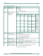


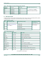


Table 6. Switch settings (continued)
Switch
Supported function
Description
SW5[1:2]
SoC use
SW_CPU_FORCE[1:0]
• 0x: Normal mode (default setting)
• 10: Reserved
• 11: Force LS1028
Do not change the default setting of this switch.
NOTE
SW5[3]
Bypass mode
SW_BYPASS_B
• 0: Disable thermal monitors and other alarms
• 1: Normal operation (default setting)
SW5[4]
Write protect
SW_CFG_WP
• 0: Allow write to SYSID and UEFI flash
• 1: Write-protect SYSID and UEFI flash (default setting)
SW5[5]
Boot Box mode
SW_BOOTBOX_B
• 0: Enable boot-box mode
• 1: Normal operating mode (default setting)
SW5[6:7]
Unused
Reserved
Default value is 0.
SW5[8]
IEEE/SAI
• 0: Signals routed to IEEE1588 connector
• 1: Signals routed to TX-only SAI transceiver (default setting)
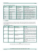
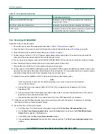
The table below summarizes the switch settings of the LS1028ARDB DIP switches for eMMC boot (SDHC2) and SD boot
(SDHC1).
Table 9. Switch settings for eMMC/SD boot
DIP switch
Setting for eMMC boot
Setting for SD boot
SW2[1:8]
1001_1000
1000_1000
SW3[1:8]
1111_0000
1111_0000
SW5[1:8]
0011_1001
0011_1001
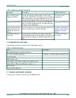
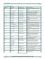
9 LEDs
The LS1028ARDB has numerous onboard light-emitting diodes (LEDs), which can be used to monitor various system functions,
such as power-on, reset, board faults, and so on. The information collected from LEDs can be used for debugging purposes.
The following table lists all the LEDs available on the top-side of the LS1028ARDB board.
on page 5 shows the position of LEDs on the board.
NXP Semiconductors
LEDs
QorIQ LS1028A Reference Design Board Getting Started Guide, Rev. 0, 2/2019
User's Guide
10 / 18