


USB to SPI Interface Evaluation Board, Rev. 1.0
Freescale Semiconductor
3
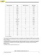
The SO signal can be connected to pin 12 (normal), pin 13 (alternate), or pin 15 (alternate) of the DB25 connector via shorting
plugs. This again is to accommodate different Freescale Evaluation Boards that at different times have used each of these pins
for the SO SPI signal.
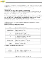
If the Evaluation Board is to be used as an interface to a Freescale Evaluation Board, the user can select the correct pin outs for
the SPI signals and Control and Data signals by using shorting jumper plugs or wire jumpers. Consult the specific Freescale
Evaluation Board documentation for the correct signal/pin definitions for the SPI and parallel control and data signals.
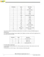
MON08 Connector
The MON08 connector consists of the following 16 pins:
4
SCLK
11
SPCLK
5
DATA0
13
PTD0
6
DATA1
14
PTD1
7
DATA2
15
PTD2
8
DATA3
16
PTD3
9
DATA4
17
PTD4
10
NC
---
-------
11
NC
---
-------
12
SO
9
MISO
13
NC (alt SO)
(9)
(MISO)
14
CNTL1
19
PTD6
15
NC (alt SO)
(9)
(MISO)
16
CNTL2
22
PTD7
17
CNTL3
7
PTC0
18
NC
---
-------
19
NC
---
-------
20
GND
44
VSS
21
NC
---
-------
22
NC
---
-------
23
NC
---
-------
24
NC
---
-------
25
NC
---
-------
* NC = No Connection
DB25 Pin Number
Name
JW32 Pin Number
JW32 Name