


USB to SPI Interface Evaluation Board, Rev. 1.0
2
Freescale Semiconductor
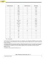
Hardware Description
The hardware Block Diagram is shown below:
The Evaluation Board consists of a MCHC908JW32FC MCU (hereafter called the “JW32”), various MCU support components
(crystal, capacitors, resistors, etc.), three LEDs, a programmable jumper matrix with a DB25 connector, a USB interface
connector (B-type), a 16 pin MON08 interface connector (to allow programming the MCU’s flash RAM), and a 4 wire SPI interface
(SI, SO, SCLK and CSB). All 5 volt power required by the Evaluation Board is obtained from either the USB or MON08
connectors. A set of two jumper select blocks configure the Evaluation Board to select which connector provides the 5 volt
power(MON08 or USB) and whether the internal 4.00 MHz crystal or external 4.9152 MHz oscillator from the P&E or FSICEBASE
unit is used. A detailed schematic is included on the accompanying CD.
LED Display
The LED’s are provided as a visual output device for debugging and test purposes. As configured from the factory, LED 2
indicates when power is applied and a USB connection is established, and LED 1 and 3 are tied to the DATA0 and CNTL0 lines,
which will be explained in detail in the Software section of this document.
Jumper Matrix
The Evaluation Board will convert USB serial data to both parallel and SPI (serial) data, which can be assigned via jumper
shorting plugs or wire jumpers to various pins on the DB25 connector. The reason for this jumper matrix feature is to
accommodate the various other Freescale Evaluation Boards that use a non-standard parallel port pinout.
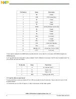
Jumper Definitions
As shipped from the factory the jumper matrix programming is as follows:
DB25 Pin Number
Name
JW32 Pin Number
JW32 Name
1
CNTL0
18
PTD5
2
CSB
8
SSB
3
SI
10
MOSI
MC68HC908JW32
MCU
USB
SPI
Parallel Outputs
MC68HC908JW32 Demo Board Block Diagram
MON08
LED’s
DB 25
FROM PC
FROM P&E
OR FSICE
MCU SUPPORT
CIRCUITRY
Jumper
Select
Matrix