


Freescale Semiconductor, Inc
FRDM-K20D50MUM
Page 16 of 17
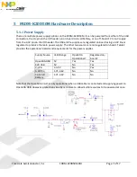
5.1.2
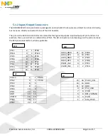
Input/Output Connectors
The K20DX128VLH5 microcontroller is packaged in an 64-pin LQFP. Some pins are utilized in on-board circuitry,
but many are directly connected to one of four I/O headers.
The pins on the K20 microcontroller are named for their general purpose input/output port pin function. For
example, the 1
st
pin on Port A is referred to as PTA1. The I/O connector pin names are given the same name as
the K20 pin connected to it, where applicable.
PTE1
2
1 PTD0
PTE0
4
3 PTC11
PTA5
6
5 PTC5
PTD4
8
7 PTC6
PTC8
10
9 PTC7
PTA1
12
11 PTA4
PTC3
14
13 PTD7
PTC4
16
15 PTC9
PTA12
2
1 PTA13
PTA2
4
3 PTC10
PTC2
6
5
PTD2
8
7
PTD3
10
9
PTD1
12
11
GND
14
13
VREFH
16
15
PTB3
18
17
PTB2
20
19
ADC0_DM0
11
12 PTB0
ADC0_DP0
9
10 PTB1
ADC0_DM3
7
8 PTD5
ADC0_DP3
5
6 PTD6
CMP1_IN3
3
4 PTC1
CMP0_IN5
1
2 PTC0
15
16 P5-9V_VIN
13
14 GND
11
12 GND
9
10 P5V_USB
7
8 P3V3
5
6 RST_TGTMCU
3
4 P3V3
1
2 SDA_PTD5
J19
J10
J9
J2