


Freescale Semiconductor, Inc
FRDM-K20D50MUM
Page 13 of 17
5.1.4
USB Interface
The Kinetis K microcontrollers feature a dual-role USB controller with on-chip full-speed and low-speed
transceivers. The USB interface on the FRDM-K20D50M is configured as a full-speed USB device.
VREGIN must be powered to enable the internal circuitry of USB (by jumper J7)
5.1.5
Serial Port
The primary serial port interface signals are PTB0 UART0 RX and PTB17 UART0_TX. These signals are connected
the OpenSDA
5.1.6
Reset
The RESET signal on the K20 is connected externally to a pushbutton, SW1, and also to the OpenSDA circuit. The
reset button can be used to force an external reset event in the target MCU. The reset button can also be used
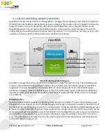
to force the OpenSDA circuit into bootloader mode. Please refer to section 5.2, Serial and Debug Adapter
(OpenSDA), for more details.
5.1.7
Debug
The
MK20DX128VLH5 supports JTAG and SWD debug interface however only SWD debug interface is available
on FRM-K20D50M board. However, an unpopulated 10-pin (0.05”) Cortex Debug connector, J6, provides access
to the SWD signals. The Samtec FTSH-105-02-F-D or compatible connectors can be added to the J6 through-hole
debug connector to allow for an external debug cable to be connected.
5.1.8
Capacitive Touch Slider
Two Touch Sense Input (TSI) signals, TSI0_CH11/PTB18, and , TSI0_CH12/PTB19 are connected to capacitive
electrodes configured as a touch slider. Freescale’s Touch Sense Software (TSS) provides a software library for
implementing the capacitive touch slider.
5.1.9
3-axis Accelerometer
A Freescale MMA8451Q low-power, three-axis accelerometer is interfaced through an I
2
C bus and two GPIO
signals as shown in Table 4 below. By default, the I
2
C address is 0x1D (SA0 pulled high).