


Freescale Semiconductor, Inc
FRDM-K20D50MUM
Page 11 of 17
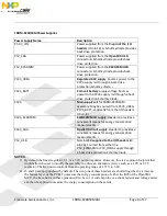
Feature
Description
Ultra low power
-11 low-power modes with power and clock gating for optimal peripheral
activity and recovery times. Stop currents of <190 nA (VLLS0), run currents of
<280 uA/MHz, 4 µs wake-up from Stop mode
-Full memory and analog operation down to 1.71V for extended battery life
-Low-leakage wake-up unit with up to eight internal modules and sixteen pins
as wake-up sources in low-leakage stop (LLS)/very low-leakage stop (VLLS)
modes
-Low-power timer for continual system operation in reduced power states
Flash, SRAM and
FlexMemory
-32 KB-128 KB flash featuring fast access times, high reliability, and four levels
of security protection
-16 KB of SRAM
-2 KB of FlexMemory (user-segmentable byte write/erase EEPROM for data
tables/system data)
-EEPROM with over 10M cycles and flash with 70 µsec write time (brownouts
without data loss or corruption)
-No user or system intervention to complete programming and erase functions
and full operation down to 1.71V
-FlexNVM adds up 32 KB for extra program code, data or EEPROM backup
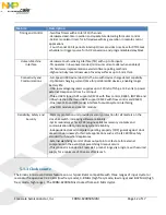
Mixed-signal capability
-High-speed 16-bit ADC with configurable resolution
-Single or differential output modes for improved noise rejection
-500 ns conversion time achievable with programmable delay block triggering
-Two high-speed comparators providing fast and accurate motor over-current
protection by driving PWMs to a safe state
-Optional analog voltage reference provides an accurate reference to analog
blocks and replaces external voltage references to reduce system cost
Performance
-50 MHz ARM Cortex-M4 core with DSP instruction set, single cycle MAC, and
single instruction multiple data (SIMD) extensions
-Up to four channel DMA for peripheral and memory servicing with reduced
CPU loading and faster system throughput
-Cross bar switch enables concurrent multi-master bus accesses, increasing bus
bandwidth
-Independent flash banks allowing concurrent code execution and firmware
updating with no performance degradation or complex coding routines