


EVB-VF522R3 Platform User’s Guide, Rev. 0, 11/2014
Freescale Semiconductor, Inc.
27
User I/O and control
14.5
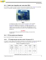
Radio tuner daughtercard connector (P24)
The EVB has a connector to allow a Silicon Labs radio tuner daughtercard (see
) to be fitted.
There are no hardware configuration options on the EVB in relation to the tuner card.
Figure 26. Radio tuner daughtercard
NOTE
The daughtercard Reset input is connected to output 2 of the Peripheral
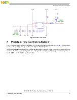
Reset-Control Multiplexer (see
Section 7, “Peripheral reset-control
”). When reset, its outputs are in the high-impedance state, but,
thanks to a pull-down resistor on the reset line, the daughtercard is reset
until the line is actively driven by the MCU via the Peripheral Reset-Control
Multiplexer.
CAUTION
Ensure that the EVB is powered OFF prior to fitting or removal of the
daughtercard.
14.6
I
2
C Connectors and headers
Refer to the EVB-VF522R3 Schematic for details.
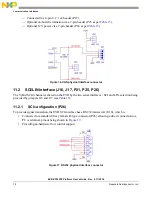
14.6.1
I
2
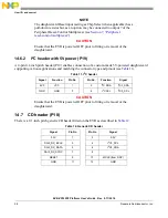
C Daughtercard connector with 3.3V power (P17)
A 10-pin 0.1” pitch connector (P17) enables connection of a custom-made 3.3V-powered daughtercard
supporting various applications and matching the connector type and pinout (see
).
Table 10. I
2
C daughtercard connector
Signal
Function
Pin No
Pin No
Function
Signal
FB_AD28
I
2
C SCL
1
2
GND
GND
FB_AD27
I
2
C SDA
3
4
---
---
3V3
VCC
5
6
---
---
---
---
7
8
Reset
I
2
C_RST
---
---
9
10
---
---