


EVB-VF522R3 Platform User’s Guide, Rev. 0, 11/2014
Freescale Semiconductor, Inc.
11
Clocking scheme
5
Clocking scheme
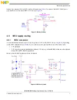
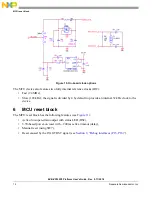
There are three on-board clock sources available–a crystal-based (Y4) 32.768 kHz MCU built-in oscillator
and two 24 MHz ones:
•
Crystal-based (Y3) MCU built-in oscillator used on the EVB by default (with R621 configured as
per
Table 15
),
•
Optional external oscillator (Y2), and
demonstrates how its 3.3V-rated output is
connected to a 1.1V-rated MCU input for applications requiring a high-quality clock source.
When Y2 is used, the Y3-based circuit (Y3, C63, C66, and R640) shall be unpopulated.
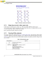
3.3V
Switch-Mode
MCU reset circuitry
External 24 MHz oscillator (optional)
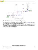
Peripheral reset-control multiplexer
Mode configuration (BOOTMOD[0..1] and RCON[0..31] pull-up resistors)
Debug (JTAG and Cortex) headers
CAN transceiver
LIN transceiver
SCI transceiver
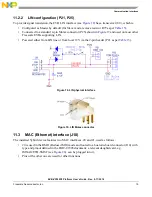
Board-to-Board MAC (Ethernet) connector
USB circuitry
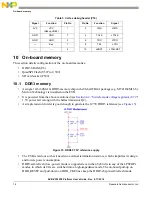
QuadSPI Flash
SD connector
DCU daughtercard connector
MLB daughtercard connector
Push button preset switches
Audio DSP circuitry (directly and via 3V3_Audio)
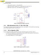
SPI Serial Flash (optional usage)
“Aux In” audio ADC circuitry (via 3V3_Audio)
Microphones Left & Right (via 3V3_Audio)
Audio DACs (via 3V3_Audio)
Radio Tuner daughtercard connector
Generic CD connector
Bluetooth daughtercard connector
I
2
C daughtercard connector
1.5V
Switch-Mode
DDR3 SDRAM circuitry
3.3V
Linear
ADC potentiometer
1.8V
Linear
DCU daughtercard connector
Audio DSP circuitry
Headphone amplifiers (via 1V8_Audio)
Table 2. EVB peripherals power