


EVB-VF522R3 Platform User’s Guide, Rev. 0, 11/2014
Freescale Semiconductor, Inc.
9
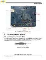
Power management scheme
4.7.1
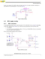
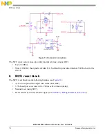
Measuring main 3.3V current
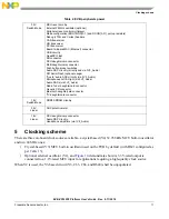
Table 15
) is intended for measuring current in the MCU 3.3V power rail.
Diode DD2 in parallel to it guarantees the 3.3V power is uninterrupted even when J9 open.
Figure 8. Measuring MCU 3.3V rail current
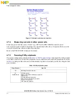
4.7.2
Measuring USB PHY current
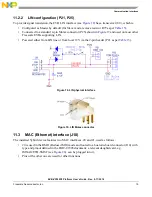
Headers J4 and J7 controlling power for the MCU USB PHYs (see
Section 11.4, “Dual USB interface (P1,
”) may also be used to measure current if their jumpers are replaced with an ammeter (see
and
Table 15
).
4.7.3
Measuring 1.2V current
Due to layout constraints, there is no dedicated header to measure the MCU 1.2V current, but it can be
done if a 0-Ohm resistor in the R28 location (see
and
Table 15
) is replaced with a current-sense
one. For user’s convenience, eight 0.02-Ohm 1% current-sense resistors are provided on the board (see
).