


Summary of Jumper and Connector Settings
Name Reference
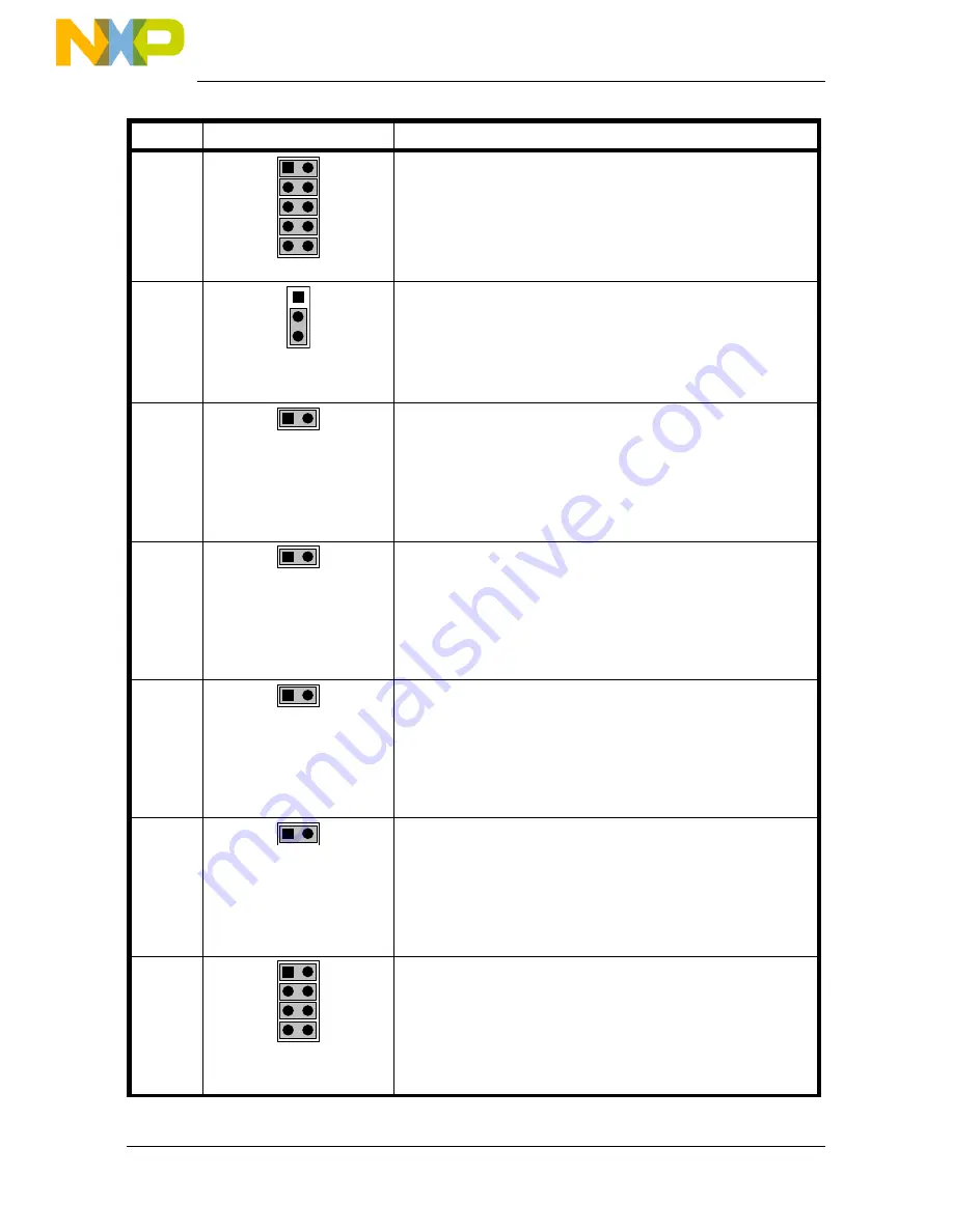
Description/Pinout
J402
TX
1
RX
EN
ERR#
STB#
CAN ENABLE
All Installed:
The CAN transceiver is connected to
the microcontroller (default)
Not Installed:
The CAN transceiver is not connected to
the microcontroller
J502
1
2
3
POWER SELECTION
1-2 (“UNREG”):
The power supply is taken from the
power supply connector (J501)
2-3 (“USB”):
The power supply is taken from the
USB connector (default)
J503
PUSH-BUTTON “PP0” ENABLE
Installed:
The “PP0” push-button is connected
to the microcontroller’s PP0 line
(default)
Not Installed:
The “PP0” push-button is not connected
to the microcontroller
J504
PUSH-BUTTON “PP1” ENABLE
Installed:
The “PP1” push-button is connected
to the microcontroller’s PP1 line
(default)
Not Installed:
The “PP1” push-button is not connected
to the microcontroller
J505
POTENTIOMETER ENABLE
Installed:
The “PAD00” potentiometer is
connected to the microcontroller’s
PAD00 line (default)
Not Installed:
The “PAD00” potentiometer is not
connected to the microcontroller
J506
PHOTO RESISTOR ENABLE
Installed:
The photoresistor network is
connected to the microcontroller’s
PAD01 analog input (default)
Not Installed:
The photoresistor network is not
connected to the microcontroller
J507
1
DIP-SWITCH ENABLE
Installed:
The DIP-switches are connected to
PB[3..0] ports of the microcontroller
(default)
Not Installed:
The DIP-switches are not connected to
the microcontroller
Page 20