background image

CONFIGURATION INSTRUCTIONS

The NV-ET1804 TBus transmitter delivers high bandwidth encrypted Ethernet signals over virtually any kind of wire (Coax, UTP, STP, Un-twisted
wire, etc.). To provide utmost signal integrity and security, the NV-ET1804 transceivers 

must be configured

to communicate exclusively with other

transceivers within their

TBus Network Group

. This group typically consists of one or more remote Transmitters, typically located at the IP camera

and one Receiver, typically located at the control-room. Transmitters may be the NV-ET1801 or NV-ET1804. The Receiver may be the NV-ET1801,
NV-ER1804, NV-ER1808i, or NV-ER1816i.

Before functioning on the network, 

each NV-ET1804 must learn which other transceivers are to be part of that group

. This simple process

is called Joining. It is recommended that transceivers in each Network Group be configured 

prior to deployment

using these instructions:

Step One: Gather Materials

• All 1800 series Transceivers

• Device labels

• RJ45 patch-cord

• IP Network Documentation Log

• Small paper-clip, partially straightened

Step Two: Connect Hardware

• Remove and discard the “Configure Before Use” labels.
• Use an RJ45 or BNC patch-cord to connect the TBus ports 

of two Transceivers.

CAUTION: Never connect the RJ45 TBus port to an 
RJ45 ethernet port

.

• Apply power to one of the TBus devices.
• The blue POWER LED on each Transceiver will blink for 8 seconds and 

then go on.

• After 20 seconds, verify that the green TBus Link LED on each transceiver is off.

If a TBus Link LED is on, the Transceiver has been previously joined.
Perform the un-joining process below before proceeding.

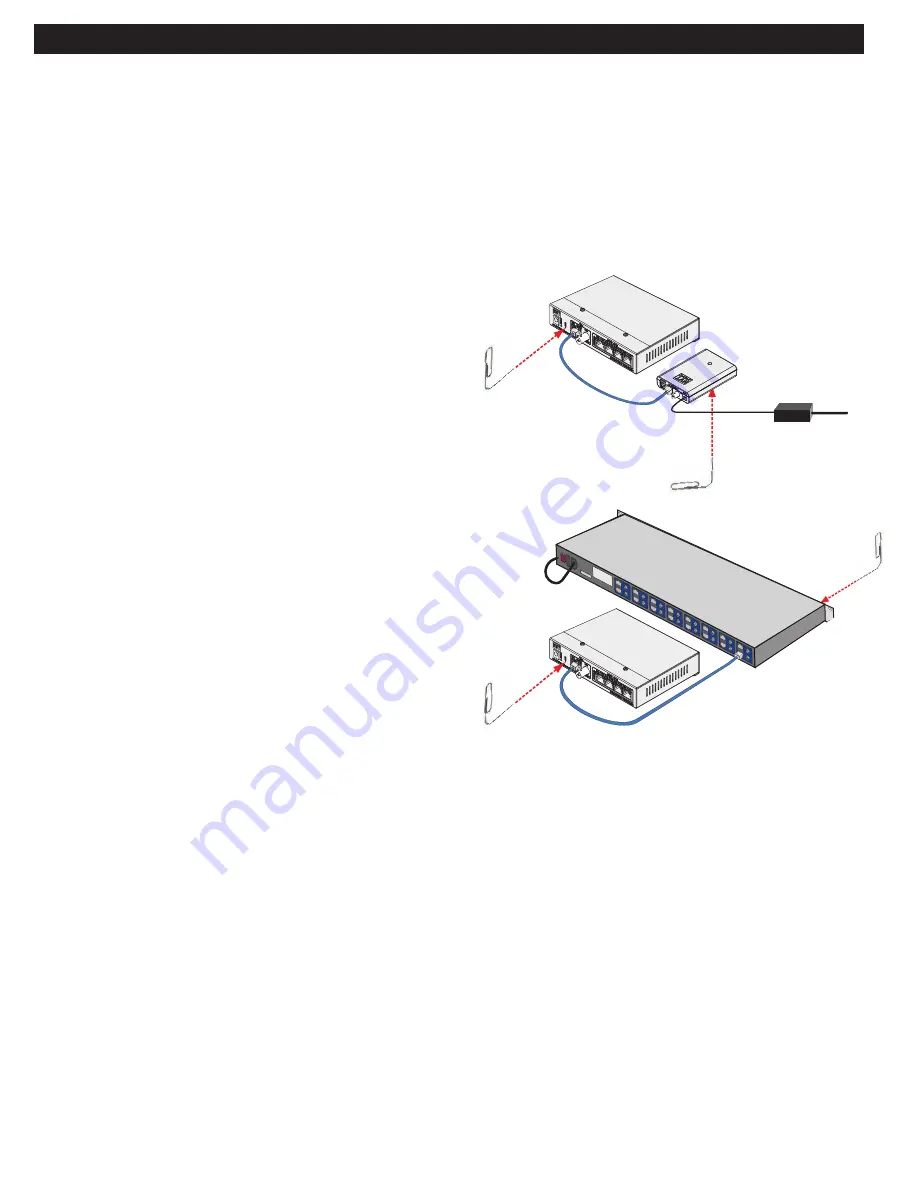
Step Three: Joining

• On Transceiver #1, using the straightened paper-clip, momentarily depress and release 

the small JOIN push-button located on the bottom of the unit. Its blue Power LED 
will begin blinking.

• Depress and release the same push-button on the Transceiver #2. Its blue 

Power LED will begin blinking.

• Both Transceivers have now entered 

Join Mode

. They will find each other 

and establish encrypted communication. In about 10 seconds, the blue Power 
LEDs on both Transceivers will return to a steady on condition, and 
their green TBus Link LEDs will illuminate, indicating a successful 

Join

.

• One TBus Link LED will remain on solid. The other may wink with data.

Step Four: Adding Transceivers

(if required)

•  Disconnect Transceiver #1 and replace it with a new un-joined 

Transceiver.

•  Repeat steps two and three to add additional Transceivers to the same 

Network Group.

Step Five: Documentation

• Label the configured Transceivers with a unique Network Group ID of your choice.

This will help you identify them after they have been deployed.

• Record this Network Group information in your IP Network Documentation Log:

• Camera Number

• Camera-end NVT Transceiver MAC Address

• Camera Position/Location

• NVT Transceiver Network Group Name

• Camera Make & Model

• Control Room NVT Transceiver MAC Address

• Camera MAC & IP Address

• Control Room Router Port Number

• Camera Login & Password

This log may include essential documentation which will help you identify all system devices during and after deployment. The NV-ER1808i and 
NV-ER1816i user interfaces have data-entry fields for  this purpose.

Un-Joining a Transceiver

If you need to move a Transceiver from one Network Group to another, it must first un-learn its
previous Network Group and be returned to an un-joined state. Do this by:

• Apply power.
• The blue POWER LED on each Transceiver will blink for 8 seconds and then go on.
• Using the straightened paper-clip, depress the small JOIN push-button until the blue Power LED goes off (about 13 seconds).
• Un-joining is now complete.

If you are not sure that un-joining has been successful, remove and then re-apply power, and repeat.

Page 3 of 14

10/

100 P

oE

+

56VDC

Transceiver #1

Transceiver #2

56V Power Supply

J

oi

n

 B

u

tt

o

n

Joi

n B

utt

on

Transceiver #1

Transceiver #2

Joi

n B

utto

n

Join Button

Содержание NV-ET1804

Страница 1: ...tall the unit in an environment where the operating ambient temperature exceeds 185 F 85 C The ventila tion should not be impeded by covering the unit with items such as newspapers table cloths curtains etc No naked flame sources such as lighted candles should be placed on the apparatus WARNING Do not interconnect multiple power supply outputs Never use more than two power supplies within a TBus c...

Страница 2: ...s and their PoE PoE or High Power PoE cameras These transceivers are extremely simple to use with no IP or MAC addressing required Status LEDs indicate power Ethernet PoE and TBus connectivity activity quality They are backed by NVT s award winning customer support and limited lifetime warranty Distance and number of devices supported may be lower due to power supply capacity and wire voltage drop...

Страница 3: ...e the same push button on the Transceiver 2 Its blue Power LED will begin blinking Both Transceivers have now entered Join Mode They will find each other and establish encrypted communication In about 10 seconds the blue Power LEDs on both Transceivers will return to a steady on condition and their green TBus Link LEDs will illuminate indicating a successful Join One TBus Link LED will remain on s...

Страница 4: ...nnecting the Control Room End Install a TBus receiver at the control room end of the TBus building wiring This receiver may be an NV ET1801 NV ER1804 NV ER1808i or NV ER1816i Connect the TBus building wiring to the TBus BNC or RJ45 jack on the receiver If the receiver is an NV ET1801 or an NV ER1804 connect an NV PS56 60W or NV PS56 90W 56VDC power supply to the power jack on the receiver If the r...

Страница 5: ... means that multiple remote camera end transmitters may be connected together to one receiver at the control room Wire may be star topology daisy chained or any combination TBus supports virtually any type of wire including coax UTP STP even un twisted wire And different wire types can be concatenated together as needed Coax cables are connected together using BNC splitters available from NVT or e...

Страница 6: ...s sent in the direction of the camera That Report is monitored and passed on by switches and routers within the network That monitoring is called IGMP Snooping These switches and routers each keep their own Routing Table and use it to determine which ports should and should not receive each multicast stream It would be inappropriate for the switch to send a multicast stream everywhere as it would ...

Страница 7: ... we have up to 13V of allowable voltage drop on the wire The voltage will dip in proportion to the remote camera load The graph below shows what PoE power distances are supported for various loads and wire types Start with the camera wattage at the left Sometimes IP cameras are listed as to their PoE Class rather than wattage Now read over to the right until you find your kind of wire Then look up...

Страница 8: ... com Network Video Technologies 1 650 462 8100 44 0 208 977 6614 nvt com info nvt com 1 000 ft 700 ft 500 ft 10 000 ft 7 000 ft 5 000 ft 3 000 ft 2 000 ft 100 ft 300 ft 200 ft 20 000 ft 1 000 m 700 m 500 m 300 m 200 m 5 000 m 3 000 m 2 000 m 100 m 70 m 7 000 m 50 m 30 m 70 ft 50 ft 30 ft 20 m 10 m Maximum Network Data Rate Mbps 20 40 60 80 100 120 140 150 RG 11 Coax RG 6 Coax RG 59 Coax UTP Cat 5 ...

Страница 9: ...Chain Topology 328ft 100m Cat5 Cat5 Hybrid DVR or NVR LAN WAN Switch or Router any wire IP Camera IP Camera IP Camera IP Camera Cat5 IP Camera IP Camera IP Camera IP Camera Cat5 IP Camera 56VDC Power Supply Figure 6 Multi Camera Star Topology 328ft 100m 328ft 100m Cat5 Hybrid DVR or NVR LAN WAN Switch or Router any wire IP Camera NV ET1801 any wire IP Camera NV ET1801 any wire IP Camera NV ET1801 ...

Страница 10: ... Station or Access Control Interface 12VDC Audio in Audio out Microphone Speaker Louroe AOP SP70 Bidirectional Audio GE IFS SP PoE 12V 1Amp Power Splitter 328ft 100m IP Camera IP Camera IP Camera IP Camera Cat5 IP Camera NV ET1804 NV ET1804 or or or NV ET1801 NV ER1804 NV ER1808i NV ER1816i 56VDC Power Supply or or or NV ET1801 NV ER1804 NV ER1808i NV ER1816i Coax Coax UTP wire Network Video Techn...

Страница 11: ...t Transmitter Netw ork Video Technologies Link Data 1 PoE Data 4 PoE Data 3 PoE Data 2 PoE 50W PoE n o Eth er ne t no an alog Quality 10 100 PoE 56VDC JOIN LINK NV ET1804 Ethernet Transmitter Netw ork Video Te chnologies no Ethe rnet no an alog TM 1 4 3 2 10 10 0 1 000 Tx Rx 10 100 PoE 56VDC NO ETHERNET NO ANALOG 1 2 1 3 1 4 1 5 1 6 1 11 2 3 4 5 6 7 8 9 0 1 Auxiliary 10 100 1000 10 100 1000 NV ER1...

Страница 12: ...56 60W 56V DC power supply 60 watts with IEC line cord NV PS56 90W 56V DC power supply 90 watts with IEC line cord Do not use with NV ER1808i or NV ER1816i NV BNCT BNC T adaptor NV EC4BNC 1 4 BNC splitter adaptor NV BNCA BNC Screw terminal adaptor NV RJ45A RJ45 Screw terminal adaptor NV PC4PR RJ45 Patch Cord 4 pair 3 1m Grey ...

Страница 13: ...ed Lifetime Specifications subject to change without notice L E D S TAT U S I N D I C AT O R S M E C H A N I C A L E N V I R O N M E N TA L Body Dimensions 6 00 in 152 mm wide 1 39 in 35 mm high 4 40 in 112 mm deep excluding connectors Shipping weight 1 20 lb 0 54 Kg Operating storage temperature 40 F to 185 F 40 C to 85 C 20 to 85 relative humidity non condensing Power consumption 3W Generated he...

Страница 14: ...r obligation on the part of NVT with respect to any of the products In the event that any of the products is dam aged altered or modified without the express written consent of NVT any warranty for those products will cease and NVT will have no further liability as it pertains to those products NVT assumes no responsibility for damages or penalties incurred resulting from the use of this product i...

Отзывы: