background image

VME Subrack System 7 U

Safety

20836-715/-718

www.schroff.biz

3

R1.1, November 14, 2008

1.5  References and Architecture Specifications

User Manual VME Backplanes
Order no.: 73972-103

Short Form User Manual VME J1/J2 Monolithic Backplanes
Order no.: 73972-128

User Manual Fan Control Module (FCM)
Order no.: 73972-083

For more information see the catalogue „Electronic Packaging“ and at  

www.schroff.biz

Содержание 20836-715

Страница 1: ...VME Subrack System 7 U User Manual Product Numbers 20836 715 20836 718 Revision R1 1 November 14 2008 Doc No 63972 148...

Страница 2: ...EN ISO 9001 2000 The company cannot accept any liability for errors or misprints The company reserves the right to amendments of technical specifications due to further development and improvement of...

Страница 3: ...2 3 VME Backplane 6 2 4 Power Supply 7 2 4 1 Grounding 7 2 5 Thermals 10 2 6 Fan Control Module FCM 11 2 7 Chassis Monitoring Module CMM optional 12 2 8 Display Module 13 3 Installation 14 3 1 Unpack...

Страница 4: ...VME Subrack System 7 U 20836 715 718 www schroff biz II R1 1 November 14 2008...

Страница 5: ...valid approval for this unit In order to enable stand alone functionality additional elements are required An operational system is achieved only by way of appropriate VME boards The completion and f...

Страница 6: ...hazard symbol It indicates that there are dangerous voltages inside the Shelf Caution This is the user caution symbol It indicates a condition where damage of the equipment or injury of the service pe...

Страница 7: ...nces and Architecture Specifications User Manual VME Backplanes Order no 73972 103 Short Form User Manual VME J1 J2 Monolithic Backplanes Order no 73972 128 User Manual Fan Control Module FCM Order no...

Страница 8: ...CM for fan monitoring controlling Display module Mains line switch The power supply is assembled on the bottom hinged rear panel 3 Axial fans the Fan Control Module FCM and the Display Module are loca...

Страница 9: ...erview Figure 1 Mechanical Overview 10006823 1 Front card cage with guide rails 6 Fan Control Module FCM 2 Fan Tray 7 VME Backplane 3 Display module 8 Axial fans 4 Power supply 9 AC terminal with line...

Страница 10: ...ep The lower guide rails are fitted with ESD clips 2 3 VME Backplane The 6 U Backplane J1 J2 Monolithic is compliant to VITA 1 1994 VITA 38 Systemmanagement for VME The subrack systems 20836 715 718 h...

Страница 11: ...th hazardous voltage Always remove mains line connector before carry out any assembly work Caution Your system has not been provided with a AC power cable Purchase a AC power cable that is approved fo...

Страница 12: ...t voltage nominal 100 240 VAC Mains Frequency 50 60 400 Hz Output max 444 W 400 W if U 200 VAC Output voltages 5 0 12 0 12 0 V V V 60 10 4 A A A Ripple 1 Dynamic response 2 or 100 mV with 25 load step...

Страница 13: ...VME Subrack System 7 U Product Definition 20836 715 718 www schroff biz 9 R1 1 November 14 2008 Figure 3 Block Diagram 10006820...

Страница 14: ...nters the subrack at the bottom panel into the Fan Tray and passes across the hot components on the Front Boards Heat is carried away by forced convection The air exits the Subrack at the top The fan...

Страница 15: ...M The highest temperature level is the reference for the fan speed If one ore more sensors exceed 60 C the output for the temperature fail LED and a digital output are activated Since the fan speed is...

Страница 16: ...ing via RS 232 or Ethernet interface The front panel provides a RJ45 connector Ethernet an a D Sub9 connector RS 232 A user interface via HTML page is available The CMM can monitor the 3 VME voltages...

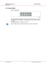
Страница 17: ...ule Figure 6 Display Module The Display Module is located at the lower front side of the subrack 3 green LEDs signal the 3 VME voltages two red LEDs signal over temperature and fan fail events The Dis...

Страница 18: ...r possible If installation in an enclosed rack is unavoidable ensure that the rack has adequate ventilation Maintain ambient airflow to ensure normal operation If the airflow is blocked or restricted...

Страница 19: ...onstructed to support the weight and dimensions of the Shelf Install any stabilizers that came with your equipment rack before mounting or servicing the system in the rack Load the rack from the botto...

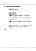
Страница 20: ...completely 5 Attach the new Backplane with two M2 5 screws and isolating washers at the top and the bottom but do not tighten the screws 6 To align the Backplane insert a VME board in the outer guide...

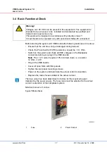
Страница 21: ...r panels Tighten the rear panel mounting screws Power on the system and determine the actual current consumtion Replace the mains fuses suitable to the actual current Figure 7 Mains Fuses Warning Volt...

Страница 22: ...t designated as a device A CE symbol is therefore not required However the systems comply with all requirements Each individual component complies to the EMC standard 89 336 EWG and to the low frequen...

Страница 23: ...s mains line switch and line filter 1 Open Frame power supply 444 W with wide range input 100 VAC to 240 VAC with 3 voltages 5 V 60 A 12 V 10 A 12 V 4 A 1 Complete AC DC wiring 1 Display module 3 Spee...

Страница 24: ...n up to 444 W Cooling 3 x 24 VDC Fans Each 170 m h 100 cfm Ambient Temperature Operating 0 C to 40 C Storage 40 C to 85 C Humidity permissable Humidity 30 to 80 non condensing EMC the system meets the...

Страница 25: ...mensions 20836 715 718 www schroff biz 21 R1 1 November 14 2008 6 Mechanical Dimensions Figure 8 Mechanical Dimensions 10006825 1 HE 1 U 1 TE 1 HP 6 HE 3 5 5 4 7 5 1 6 0 8 4 T E 3 6 T E 4 8 T E 6 HE F...

Страница 26: ...VME Subrack System 7 U Mechanical Dimensions 20836 715 718 www schroff biz 22 R1 1 November 14 2008...

Страница 27: ......

Страница 28: ...SCHROFF GMBH www schroff biz Langenalberstr 96 100 Tel 49 0 7082 794 0 Fax 49 0 7082 794 200 D 75334 Straubenhardt...

Отзывы: