


NuMaker-HMI-MA35D1-S1
Nov. 2, 2022
Page
53
of 99
Rev 1.01
N
UMA
K
E
R
-HMI
-M
A
3
5D1
-S1
U
S
E
R M
A
NU
A
L
Ma
k
er Nu
-m
be
d
NUC
47
2
Us
er Man
ua
l
4
QUICK START
This chapter guides users step by step to start the NuMicro NuMaker-HMI-MA35D1-S1 evaluation
environment based on the assembled boards: NuMaker-SOM-MA35D16A81 board, NuMaker-BASE-
MA35D1B1 board and TFT LCD daughter board. After the steps are completed successfully, users can
see the demonstration on the LCD screen and try to operate the demonstration on the LCD screen by
finger touch. For more detailed information and description about the board hardware setting and
configuration of NuMaker-SOM-MA35D16A81 board and NuMaker-BASE-MA35D1B1 board, please
see the Hardware Configuration chapter.
4.1
Hardware Setup and Power On
4.1.1
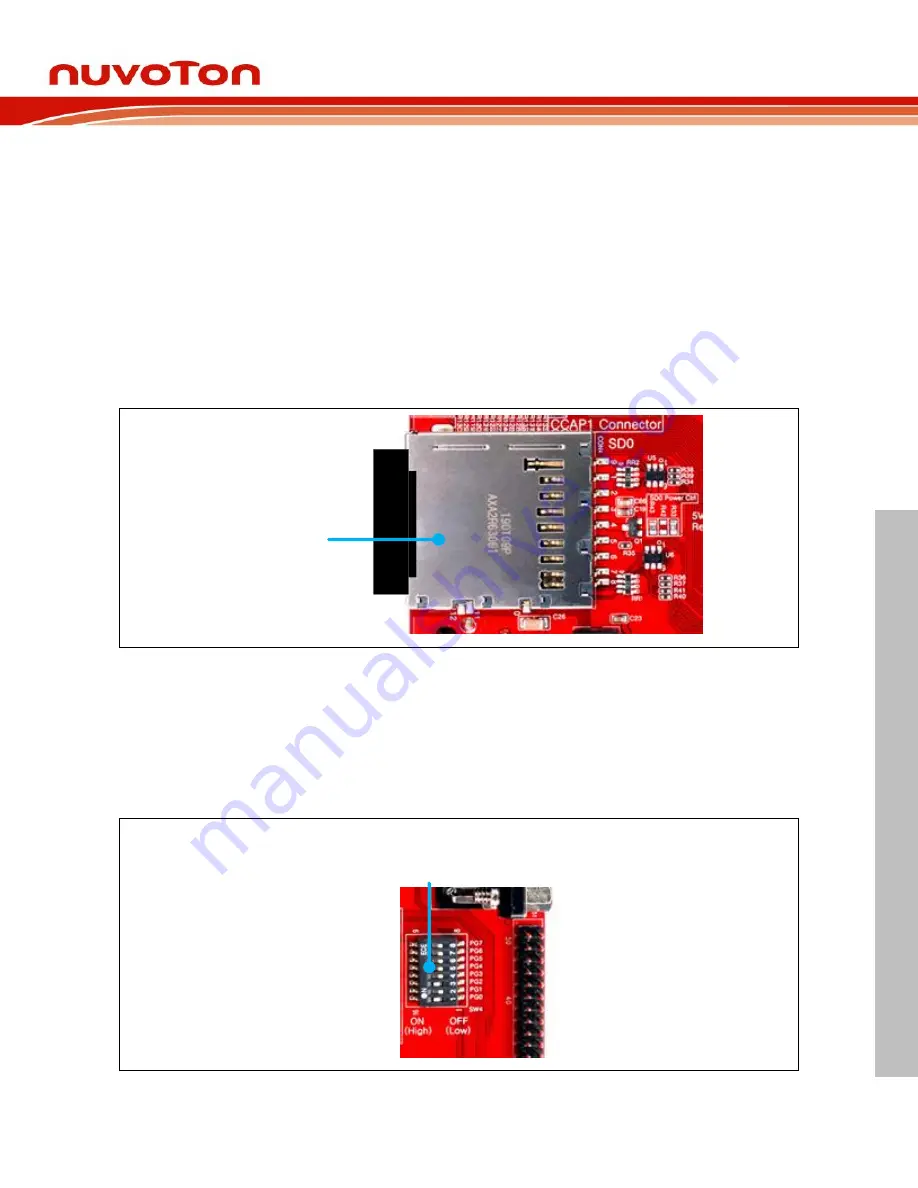
Insert SD Card
The first step is to insert the Standard SD card that had been programmed with an image file by Nuvoton
to the SD0 Standard-SD card slot (CON4) on the NuMaker-BASE-MA35D1B1 board.
SD0
Standard-SD
(CON4)
Figure 4-1 SD0 Standard-SD Card Slot (CON4)
4.1.2
Configure Power-on Setting
The second step is to make sure the power-on setting for the booting source selection on the DIP Switch
(SW4) that followed the correct ON/OFF states shown the following Table 4-1 and Table 4-2.
After choosing the correct power-on setting on these DIP switches, the evaluation environment will boot
from the image stored in the Standard-SD card when power is supplied to the NuMaker-BASE-
MA35D1B1 board.
Power-on Setting
DIP Switch
(SW4)
Figure 4-2 Power-on Setting DIP Switch (SW4)


