background image


DV TURBO SERIES DVR 

53

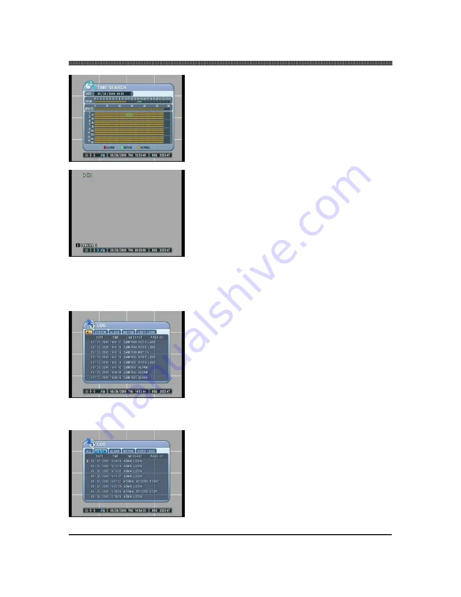
To select a specific camera to review, select a slot from the 
numbered bars.  The illustration to the left has selected 
channel 2 at 9:25 in the morning on May 26, 2005.   


Channel 2 will be displayed in full screen mode starting 
playback of the data exactly at 9:25 in the morning on May 
26, 2005. Any channel number or the DISPLAY button may 
be pressed to change the display mode.   


5.2 LOG SEARCH 


The logs can be used to search and review directly to a point in time of the recorded data.  Alarm, motion, 
video loss and system related logs can be searched and played back directly from the time of the incident.   

 
Press the LOG button to access the log submenu.  Use the 
directional buttons to navigate to the desired log.  UP and 
DOWN buttons are used to navigate through the list of the 
logs, and LEFT and RIGHT buttons to navigate through 
different pages.  Pressing the Enter button at the desired 
log will start the playback. 


System related logs and video loss logs will be played back 
in multi channel view mode.   


Содержание DV turbo NVDV4-16000

Страница 1: ...DV TURBO SERIES DVR 0...

Страница 2: ...box 1 Digital Video Recorder 2 Remote Controller 3 DVR Client Software CD 4 Power Cable 5 Two AAA Batteries 6 RS232 to Eight RCA Audio Input Cables Two for NVDV4 16000N 7 RS232 to RS422 485 Adapter 8...

Страница 3: ...lost data due to a mistaken operation or malfunction of the Digital Video Recorder the software the hard drives personal computers peripheral devices or unapproved unsupported devices Trademark Ackno...

Страница 4: ...this equipment does cause harmful interference to radio or television reception which can be determined by turning the equipment off and on the user is encouraged to try to correct the interference by...

Страница 5: ...le The Privacy act of 1974 5 U S C 552a Please note that NUVICO Digital Video Recorders are intended for recording of surveillance use and should never be used in a manner that invades other people s...

Страница 6: ...should be conducted by qualified service personnel authorized by the equipment distributor or NUVICO customer help desk Stop operating the equipment immediately if it emits smoke or noxious fumes Fai...

Страница 7: ...to overheating distortion of the equipment fire electrical shock or other hazards Do not place the battery near a heat source or expose it to direct flame or heat Neither should you immerse them in wa...

Страница 8: ...re or high humidity Use the device at temperatures within 41 F 104 F and humidity below 90 The normal operating power source for this device is 110V 220V AC 50 60Hz PREVENTING MALFUNCTION Avoid Strong...

Страница 9: ...20 Screen Position Adjustment 20 II BASIC OPERATION 21 1 MAIN SCREEN 21 2 INFORMATION LOG LIST 22 2 1 INFORMATION 22 2 2 LOG 25 2 2 1 All 25 2 2 2 System 25 2 2 3 Network 26 2 2 4 Alarm 26 2 2 4 Motio...

Страница 10: ...57 1 1 6 Split Mode 57 1 2 SEQUENTIAL SETUP 58 1 2 1 Sequence Interval 58 1 2 2 Sequence Mode 58 1 2 3 Full Screen 58 2 CAMERA 59 2 1 CAMERA SELECTION 59 2 1 1 Covert 59 2 1 2 Brightness 60 2 1 3 Con...

Страница 11: ...SYSTEM REQUIREMENT 90 2 INSTALLING DVRPLAYER 90 3 EXECUTING DVRPLAYER 92 4 DVRPLAYER 93 1 MAIN CAMERA DISPLAY WINDOW 93 2 CAMERA DISPLAY SELECTION 93 3 MODE DISPLAY 93 4 TIME AND DATE 93 5 MODE SELEC...

Страница 12: ...EXT MENU 115 1 Channel Context Menu 115 2 DVR Context Menu 115 3 Virtual DVR Context Menu 116 8 DVR SETUP 117 VI WEB CMS 122 1 CONNECTING TO THE UNIT VIA INTERNET EXPLORER 122 1 1 USERS WITH THE WINDO...

Страница 13: ...DV TURBO SERIES DVR 12 QUICK START PAGE The Factory Default password for the unit is 000000 The Default password to run the CMS software is 0...

Страница 14: ...Digital Video Recorder along with the remote controller The LOCK LED light is turned on when this feature is activated To unlock press the lock button again and enter the password when prompted 5 BAC...

Страница 15: ...play screen this button is used to hide the On Screen Display information such as time date and channel icons This button also removes any of the alert icons on the screen AL VL and PL 16 RECORD STOP...

Страница 16: ...LE HOLD This button allows the user to maintain the selected playback or reverse search speed To select search speed rotate the shuttle ring to the desired position then press the SHUTTLE HOLD button...

Страница 17: ...ple RCA connectors 4 AUDIO OUTPUT Two RCA jack connectors 5 75 OHM TERMINATION SWITCH Video signal termination for loop outs 6 USB 2 0 PORT 7 RJ45 ETHERNET PORT 10 100Base T RJ45 Ethernet Port for net...

Страница 18: ...onitor output 13 MODEM RS 232C 9 Pin port connector to connect an external modem 14 RS 485 RS 422 9 Pin port connector to connect PTZ cameras or keyboard controllers 15 OPTION Development purposes onl...

Страница 19: ...REMOTE CONTROLLER STOP PLAY POWER PAN TILT ZOOM BACK UP DVR ID MENU LOG FAST FORWARD DISPLAY MODE SCHEDULE REC ON OFF ENTER INFORMATION CANCEL OSD OFF EXT SEARCH REWIND NUMBERS ALPHABET TIME SEARCH ZO...

Страница 20: ...8 9 10 11 12 13 14 15 16 IN1 IN3 IN5 IN7 IN2 IN4 IN6 IN8 OUT1 OUT2 75Ohm USB ETHERNET S VIDEO COMPOSITE SPOT OUT VGA MODEM RS 485 OPTION AC IN 110 230V 1 2 3 4 G 5 6 7 8 G 9 10 11 12 G 13 14 15 16 G...

Страница 21: ...other operation of the Digital Video Recorder it is important to setup the time and the date Please refer to page 86 for setting the time and the date on the DVR Screen Position Adjustment The screen...

Страница 22: ...ive space counter Moreover it will also address several live view modes the DVR has to offer which include several multiple channel view modes automatic sequence modes and the channel swapping feature...

Страница 23: ...formation about the DVR Press MENU to access the main setup window and then select SYSTEM to access system setup When the MENU button is pressed a prompt for the administrator s password will appear S...

Страница 24: ...the Host Name LANGUAGE Displays the current user interface language NETWORK Displays the current IP address and the port of the DVR MCU VERSION Displays the Micro Controller Unit version FPGA VERSION...

Страница 25: ...ormation about the USB compliant device attached at the rear USB slot of the DVR IDE BUS 0 Displays the status of the devices that are connected to Primary HDD Cable IDE BUS 1 Displays the status of t...

Страница 26: ...nts related to the operation and alerts of the DVR are listed and sorted under ALL in chronological order starting with the most recent 2 2 2 System Any event related to the operation of the system is...

Страница 27: ...2 2 4 Alarm Any alarm activity is listed and sorted under ALARM in the same chronological order 2 2 4 Motion Any motion activity is listed and sorted under MOTION in the same chronological order 2 2...

Страница 28: ...numerous display modes from single quad 6 7 8 9 13 and 16 channel display modes The single channel display mode can be accessed directly by pressing the appropriate channel number The rest of the disp...

Страница 29: ...DV TURBO SERIES DVR 28 Live View Sequence of NVDV4 16000N...

Страница 30: ...single channel display initially and continue to sequence through all the channels in full screen mode if single channel sequencing is selected If any other display sequencing modes are selected then...

Страница 31: ...uence combined 3 3 ZOOM During live view mode or during the playback it is possible to zoom into a section of the screen to get a close up view of the section Press the zoom button to bring up the zoo...

Страница 32: ...tton to return to the normal view 3 4 SPOT OUT In addition to the Main Monitor attaching a Spot Monitor enables user to monitor specific channels independently from the main monitor By pressing onto F...

Страница 33: ...recording settings are used when the record button is pressed The factory default normal record setting is as follow RESOLUTION USE QUALITY RATE AUDIO MOTION ALL CHANNELS 360 x 240 ON HIGH 7 F S OFF O...

Страница 34: ...ay be played back in reverse paused speed search up to 16 times the normal speed or move picture by picture using the jog shuttle Please refer to the following illustrations for a detailed description...

Страница 35: ...orward or to fast rewind to the desired location During the playback mode pause the playback by pressing the STILL button or the STEP buttons on the remote controller Turn the jog dial clockwise or th...

Страница 36: ...ode The diagram to the left represents the shuttle ring and the increments that represent each fast forward or fast reverse speed 16x speed fast reverse 8x speed fast reverse 4x speed fast reverse 2x...

Страница 37: ...is always recorded in real time unlike the video data that can be recorded at various recording speeds The audio if recorded is played back automatically when in single channel view mode If the audio...

Страница 38: ...the lock LED will be lit and all buttons except the lock button will be disabled Pressing the buttons on the DVR or the remote controller will have no effect To unlock the buttons press the lock butto...

Страница 39: ...kup CD The illustration to the left has selected ALL CAMERA NORMAL ALARM and MOTION data For CD R CD RW Backup you cannot select individual channel Individual Channel Backup is only supported in USB F...

Страница 40: ...l hard disk drive offer two different backup methods MANUAL AND AUTOMATIC The manual backup procedure is the same as using the internal CD RW for backup This section will cover the automatic procedure...

Страница 41: ...ighlight the START button then press ENTER button to begin automatic backup Please note that the USB insignia s color is gray The status of the automatic backup to the external hard disk drive will be...

Страница 42: ...allows both individual channel backup and taking snap shots of individual pictures during playback After the USB Flash memory stick backup you have to manually start the Mini Player from the USB Flas...

Страница 43: ...ENTER button is pressed a snap shot will be saved onto the memory stick in JPEG format The USB insignia will change its color to blue briefly each time the button is pressed The live screen can also...

Страница 44: ...the PTZ camera Some PTZ control functions can only be accessed using the remote controller so please have the remote controller handy when using the PTZ control interface The layout of the PTZ interf...

Страница 45: ...n remote controller Press Go to button Enter the desired Preset and press Enter Start Auto Tour BACKUP on remote controller Press Auto Tour Button Press the button and enter the range of Preset and pr...

Страница 46: ...daries Button Function Set up tilt limit REC on remote controller Set down tilt limit SCHEDULE on remote controller Set left pan limit LEFT step button on remote controller Set right pan limit RIGHT s...

Страница 47: ...s can be adjusted from the ALARM setup Please note that alarm recording is independent of any recording modes Press the RECORD button and the record icon will appear as shown on the left The DVR will...

Страница 48: ...ivated the motion grid setting may be ignored Press the record button and the record icon will appear as shown on the left The DVR will be on record standby mode until motion is triggered The DVR does...

Страница 49: ...Instead of the normal REC icon the DVR will display SCHEDULE icon 4 4 COMBINATION RECORDING If a need arises to record a combination of motion alarm and scheduled recording then the DVR can be config...

Страница 50: ...and also needs to be recorded in case of an alarm triggers Both motion and alarm recording can be used to satisfy the requirement Motion recording has been activated under RECORD menu The recording r...

Страница 51: ...location needs to be recorded using only motion recording at a predetermined schedule but also needs to record in case of alarm triggers Both schedule motion recording and alarm recording can be used...

Страница 52: ...SE SCHEDULE CAMERA USE MOTION Normal RECORD ON OFF OFF OFF Motion RECORD ON OFF OFF ON Alarm ALARM OFF ON OFF OFF Schedule SCHEDULE OFF OFF ON OFF Schedule Motion SCHEDULE OFF OFF ON ON Normal and Ala...

Страница 53: ...utton to access the time search calendar Use the directional buttons to navigate to the desired date and then press the Enter button to access selected date Use the directional buttons to navigate to...

Страница 54: ...CH The logs can be used to search and review directly to a point in time of the recorded data Alarm motion video loss and system related logs can be searched and played back directly from the time of...

Страница 55: ...rt the playback in single channel view mode The illustration to the left has selected a log from the MOTION tab Alarm or motion related playback will display according icons during the playback The il...

Страница 56: ...llowing categories Directional buttons are used to navigate through all the main categories and their submenus ENTER button is used to access and save the settings and exit out of the submenus The and...

Страница 57: ...ut device and the sequential display of display modes 1 1 DISPLAY SETUP 1 1 1 Status Bar Select the display of the status bar containing various USB client connection date time remaining hard disk dri...

Страница 58: ...rk Gray Gray Blue White The default background color is Gray 1 1 5 Display Device Select the main video output CCTV Monitor composite video signal output using BNC connectors and VGA output PC Monitor...

Страница 59: ...lay modes to include in sequenced display Single quad 6 7 8 9 10 13 and 16 channel view modes can be included in the sequential display mode Selected view modes will be displayed in sequence from the...

Страница 60: ...amera associated 2 1 CAMERA SELECTION Select the camera that needs to be modified or adjusted 2 1 1 Covert Select between covert mode YES and normal mode NO If covert mode is activated the activated c...

Страница 61: ...2 1 2 Brightness Adjust the brightness using or button The default value is 50 2 1 3 Contrast Adjust the contrast using or button The default value is 50 2 1 4 Color Adjust the color using or button T...

Страница 62: ...pad driven input systems press the appropriate numeric buttons on the remote controller or on the DVR to enter the desired letters and numbers Refer to the following illustration for the sequence of v...

Страница 63: ...L 9600 bps 15 CNB AN200 9600bps 16 CANON VC C4 9600bps 17 PELCO P PROTOCOL 2400bps 18 PELCO P PROTOCOL 4800bps 19 PELCO P PROTOCOL 9600bps 20 PELCO Expanded 2400bps 21 PELCO Expanded 4800bps 22 PELCO...

Страница 64: ...RECORD TIME RECORD TIME determines the amount of the time the DVR records after the initial motion detection The user may choose from 10 to 240 seconds in 10 second intervals If additional motion is d...

Страница 65: ...level is 10 3 2 2 Motion Grid Activate or deactivate each grid by pressing the appropriate numeric button All the grids are active by default and are highlighted in blue tint If deactivated then the t...

Страница 66: ...rd and motion record options are available 4 1 USE Select the usage of the camera If the camera is set to ON then that specific camera will be used to record If set to OFF then that specific camera wi...

Страница 67: ...esolution is set to 720 x 240 then the maximum record rate is 15 pictures per second Finally if the global record resolution is set to 720 x 480 then the maximum record rate is 7 pictures per second 4...

Страница 68: ...larm buzzer and alarm output related options 5 1 RECORD SETUP 5 1 1 Use Select the usage of the camera If the camera is set to ON then that specific camera will be used to record If set to OFF then th...

Страница 69: ...e maximum record rate is 15 pictures per second Finally if the global record resolution is set to 720 x 480 then the maximum record rate is 7 pictures per second 5 1 4 Audio Select audio record ON or...

Страница 70: ...ecord Camera Record camera provides the option of two distinct recording modes when an alarm trigger occurs ALL Any alarm trigger will force all channels to record 1 1 The channel from which an alarm...

Страница 71: ...1 4 to trigger in conjunction with any of the alarm inputs If SYSTEM is selected the relays will be triggered in case of system abnormalities such as HDD FAIL FAN LOCK and so on 5 2 6 Alarm Out On Off...

Страница 72: ...e been entered If no schedule is entered the unit will prompt the user to set the schedule function 6 1 CHART The CHART displays the recording schedules configured on the DVR It breaks down the days o...

Страница 73: ...button to access ALL time entry menu Enter the time for the regular business hours 10am through 8pm and then select MODE 1 Please note that the END time is entered as 19 59 The time must be entered i...

Страница 74: ...e for all days of the week MODE 1 recording from 10am through 8pm and MODE 2 recording from 8pm through 10am Select MODE 1 and adjust the settings accordingly Select MODE 2 and adjust the settings acc...

Страница 75: ...of available IP address types STATIC IP an IP address that remains constant for the duration of the contract of the Internet service DHCP Dynamic Host Configuration Protocol a service where the IP add...

Страница 76: ...Software CMS The default value is 7000 7 4 BANDWIDTH Select the amount of network bandwidth that the DVR can utilize 7 5 E MAIL ADDRESS Enter up to five different user s e mail address The DVR will s...

Страница 77: ...ternet Service Provider The purpose of a router is to enable multiple personal computers and any other devices that require internet connection to access the internet simultaneously Most routers by de...

Страница 78: ...Open Internet Explorer then type in http 192 168 1 1 to access the router Enter the User Name and Password to access the router You will then be taken to the main menu The factory user name is blank...

Страница 79: ...DV TURBO SERIES DVR 78 Click on Application Gaming tab to access port forwarding configuration page...

Страница 80: ...e designated port 7000 for the DVR Point each port to the DVR Illustration shows that the DVR s IP address being 192 168 1 85 In the following examples DVR7000 was used Make sure you enable the port f...

Страница 81: ...Configuring the DVR to communicate with Linksys Router Go to Network in Main Menu Set the CONFIG as STATIC IP Make sure to change the information to IP ADDRESS 192 168 1 85 NETMASK 255 255 255 0 GATE...

Страница 82: ...92 168 0 250 this section will explain how to configure the computer to connect directly to the DVR The following illustration was based on a computer system running Windows XP Professional On the PC...

Страница 83: ...Right Click on the Local Area Connection icon to drop a pull down menu then click on Properties to enter the Local Area Connection Properties Double Click on the Internet Protocol TCP IP to edit the...

Страница 84: ...ss for the computer In this illustration the IP address entered is 192 168 0 50 Please note that any host address may be used as long as it does not conflict with the router s host address 1 and the D...

Страница 85: ...8 1 GENERAL 8 1 1 System ID Select the DVR s SYSTEM ID Up to 99 DVRs can be controlled using one remote controller To select the DVR to be controlled with the remote controller press and hold the DVR...

Страница 86: ...s a beep every time a button is pressed The default is ON 8 1 4 Keypad Model Select the type of keypad to be used for the DVR 8 1 5 Record Size Select the global record resolution Values are 360 x 240...

Страница 87: ...heir time and date The default is OFF ON The DVR is set to Slave DVR and synchronizes with the master DVR OFF The DVR is set to Master DVR and does not synchronize with any DVRs 8 2 2 Time Server Ente...

Страница 88: ...DV TURBO SERIES DVR 87 8 2 4 Time Enter the time in 24 hour format 8 3 PASSWORD 8 3 1 Selection Select the user to change the password 8 3 2 New Confirm Enter the new password Confirm the password...

Страница 89: ...en using CD RW media 8 4 2 Start After selecting which device to format highlight START and then press button to begin formatting Formatting will begin and the progress will be displayed at the bottom...

Страница 90: ...External HDD Select the record policy of the external hard disk drive By default the hard disk drive will overwrite from the beginning when it becomes full 8 4 5 Disk Monitor By factory default the DV...

Страница 91: ...s components and operating system The following chart displays the minimum and the recommended system specification to operate the CMS properly Minimum Recommended OS Windows 98SE Windows XP CPU Penti...

Страница 92: ...op Shortcuts The Start Menu Shortcuts and Desktop Shortcuts may be unchecked if desired Click on Next to continue Select the folder in which the program will be installed By default it is installed in...

Страница 93: ...DV TURBO SERIES DVR 92 3 EXECUTING DVRPLAYER Once you start the DVRPLAYER it will prompt you to enter a password The default password is 0 To get rid of this screen Press ESC...

Страница 94: ...e 4 channel 6 channel 7 channel 8 channel 9 channel 10 channel 16 channel 25 channel 36 channel 49 channel and 64 channel view modes All display modes are accessible no matter how many DVRs are connec...

Страница 95: ...the On Screen Display options for the cameras Time Set name DVR name Camera Number Camera name and the frame rate 2 Overlay Select the use of video overlay on or off The video overlay utilizes Micros...

Страница 96: ...motion Video Loss CMS will emit a sound when there is a Video Loss 10 PLAYBACK CONTROL BUTTONS The playback control buttons only function when reviewing downloaded files From top left in clockwise di...

Страница 97: ...Focus Far Focus Near Auto Focus 2 Iris Control Button Function Iris Open Iris Close Auto Iris 3 Tour Button Function Set preset tour positions the total number differs per camera Go To calls up preset...

Страница 98: ...n critical functions of the DVR is interrupted or has failed connection failure connection timed out disconnection power failure fan lock recovery system failure recovery and HDD failure recovery YELL...

Страница 99: ...or power failure this block will blink in red in conjunction with the NAME block NAME DVR name either the host name or something created by the user In case of network connection error or power failur...

Страница 100: ...us The status of the DVR is displayed in five different icons 1 Normal When the DVR is working within normal parameters the icon color remains blue Double click on the icon to begin live monitoring 2...

Страница 101: ...status Click on OK at the lower right corner of the screen to exit the CMS log and to clear the icon status 5 Live Monitoring When the DVR is selected to be monitored live the DVR icon is highlighted...

Страница 102: ...d camera in single channel mode Camera Status Definition 1 Camera normal non recording mode The icon color changes to cyan when the camera is connected but the DVR or the channel is not in recording m...

Страница 103: ...needs to be highlighted Auto Scan Auto Scan scans for any DVRs connected within the Local Area Network As it adds DVRs automatically it will ignore DVRs already on the list By default Auto Scan will e...

Страница 104: ...ize and arrange cameras with any of the events occurring from any cameras The cameras with events are moved to channel 1 automatically then arranged in the order of priority Alarm Check this option to...

Страница 105: ...ghlight the Virtual DVR to be removed and then click on Del Virtual Set Property Property displays general information about a Virtual DVR such as Virtual DVR name total number of cameras and IP addre...

Страница 106: ...DVR host name will be displayed if Auto Scan feature was used b Channel Status Displays the current status of each channel Indicator Status REC Normal Recording Wait Connection in progress Loss Video...

Страница 107: ...lecting a group of cameras to monitor Verify that individual DVRs are listed under DVR Window and a Virtual DVR has been created and listed under Virtual DVR Window Double Click on the Virtual DVR Sin...

Страница 108: ...cameras under Virtual DVR In the example to the left all available 12 cameras are displayed starting at channel 7 Individual cameras can be added onto the Virtual DVR by click and dragging individual...

Страница 109: ...al display is available for both individual DVRs and Virtual DVRs 1 Select a channel for playback In the example below channel 16 was selected for dual display playback 2 Right click on the selected c...

Страница 110: ...DV TURBO SERIES DVR 109 4 Select the date and the time and then click on Play...

Страница 111: ...DV TURBO SERIES DVR 110 5 The selected channel will begin playback in Dual Display Mode 6 Right click on the same channel and then select Live to revert back to the live mode...

Страница 112: ...Selector button to switch to Playback Mode Select Channel During the remote or local playback any camera can be accessed and viewed in single channel view mode by clicking on any camera number The sa...

Страница 113: ...layback one month at a time Time Displays available files for remote playback or local playback in 24 hour format It will also list any cameras with recorded video for the appropriate hour and minute...

Страница 114: ...ckward or forward in time 4 Selecting a file for download The file selection process is just as selecting a file for remote playback Additionally the user can uncheck any channel that they wish not to...

Страница 115: ...R file from which the file was downloaded from Select the date time and the minute slot and then click on Play Once the playback begins the video can be manipulated using the playback controls The vid...

Страница 116: ...features for each individual submenu type 1 Channel Context Menu Search Enters Remote Search window for single camera Full Screen Changes the display to single channel view mode 2 DVR Context Menu Li...

Страница 117: ...or MESSAGE to sort the list accordingly Setup Enters the setup dialog for the DVR Remove Remove the DVR from the DVR Window 3 Virtual DVR Context Menu Live Start live monitoring for pre configured Vi...

Страница 118: ...or OFF b Select Camera Number and Title display ON or OFF c Select the Border Line and Background colors 1 2 Display Sequential Setup a Select the Sequential Interval Time b Select the Sequential Vie...

Страница 119: ...o select smaller motion grids for more precise motion detection 4 Record a Select camera use ON or OFF b Select the record quality c Select the record rate d Select audio record ON or OFF e Select mot...

Страница 120: ...ct alarm out 1 4 options e Select Motion to Alarm ON or OFF 6 Schedule Chart Schedule setup is the same as configuring the schedule from the DVR s schedule menu 6 1 Schedule Mode 1 4 a Select camera u...

Страница 121: ...R ID b Select Auto Key Lock ON or OFF c Select Key Tone on or off d Select overwrite option for the internal hard disk drive e Select overwrite option for the external hard disk drive f Select the glo...

Страница 122: ...DV TURBO SERIES DVR 121 8 3 System Password Enter the new passwords for the users 8 4 System Control a Activate or deactivate the recording b Activate or deactivate the schedule recording a b...

Страница 123: ...HE UNIT VIA INTERNET EXPLORER Enter the IP address of the unit in the address pane of the Internet Explorer For example type in http 192 168 0 250 7000 Above illustrates example of a unit when it is u...

Страница 124: ...LOG IN PROCEDURE You can either sign in with admin or user Next enter the password for the unit Click on Web CMS Use overlay to connect to the DVR Please refer to page 85 for more information on CMS o...

Страница 125: ...DV TURBO SERIES DVR 124 Click on Install Wait until the Image Loading is complete When the Image Loading is done the WEB CMS version should appear along with the images from the DVR...

Страница 126: ...the FAQ thoroughly before contacting NUVICO Help Desk NUVICO help desk is available from Monday through Friday from 9 00am to 5 30pm Eastern Standard Time TOLL FREE 866 523 1700 TEL 201 541 1605 FAX...

Страница 127: ...DV TURBO SERIES DVR 126 Notes...

Страница 128: ...DV TURBO SERIES DVR 127 Notes...

Страница 129: ...DV TURBO SERIES DVR 128...

Отзывы: