background image

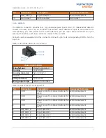
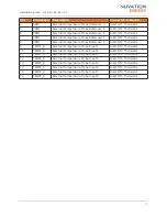
Pin

Connection

Description

Connected to Device

4

VBOT

External Temperature Probe Reference 4

10k

Ω 

NTC Thermistor

5

VBOT

External Temperature Probe Reference 5

10k

Ω 

NTC Thermistor

6

VBOT

External Temperature Probe Reference 6

10k

Ω 

NTC Thermistor

7

VBOT

External Temperature Probe Reference 7

10k

Ω 

NTC Thermistor

8

VBOT

External Temperature Probe Reference 8

10k

Ω 

NTC Thermistor

9

TEMP1_R

External Temperature Probe Input 1

10k

Ω 

NTC Thermistor

10

TEMP2_R

External Temperature Probe Input 2

10k

Ω 

NTC Thermistor

11

TEMP3_R

External Temperature Probe Input 3

10k

Ω 

NTC Thermistor

12

TEMP4_R

External Temperature Probe Input 4

10k

Ω 

NTC Thermistor

13

TEMP5_R

External Temperature Probe Input 5

10k

Ω 

NTC Thermistor

14

TEMP6_R

External Temperature Probe Input 6

10k

Ω 

NTC Thermistor

15

TEMP7_R

External Temperature Probe Input 7

10k

Ω 

NTC Thermistor

16

TEMP8_R

External Temperature Probe Input 8

10k

Ω 

NTC Thermistor

Installation Guide - 2018-10-08, Rev. 2.0

22

Содержание BMS NUV100-CI-12

Страница 1: ...Installation Guide Nuvation High Voltage BMS 2018 10 08 Rev 2 0 Copyright 2018 Nuvation Energy ...

Страница 2: ... Cells 13 Battery Cell Connecter for Cell Interface 12 channel 14 Battery Cell Connecter for Cell Interface 16 channel 16 Battery Cell Connecter for Cell Interface 12V 4 channel 19 4 3 4 Temperature Sensors 21 5 Nuvation BMS High Voltage Power Interface 23 5 1 Overview 23 5 2 Mechanical Dimensions 23 5 3 Electrical Connections 24 5 3 1 Contactors 24 5 3 2 Interlock 27 5 3 3 External Power 28 5 3 4...

Страница 3: ...Reset to Factory Defaults 37 ...

Страница 4: ...y chemistries with different current capacities and so high voltage with high current capacity may be present while connecting the Nuvation BMS You must use proper electrical safety precautions when handling any part of the Nuvation BMS Neither Nuvation Energy or any of its employees shall be liable for any direct indirect incidental special exemplary personal or consequential harm or damages incl...

Страница 5: ...ur specific target application 1 1 About this Guide This Installation Guide Nuvation High Voltage BMS provides wiring instructions to connect your Nuvation High Voltage BMS to your system Once you have successfully completed the installation process please follow instructions in the Operator Interface Guide for accessing and configuring the Nuvation BMS Operator Interface We thrive on your feedbac...

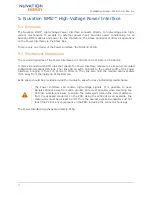
Страница 6: ... Power Interface NUV100 CI 12 Nuvation BMS High Voltage Cell Interface 12 channel NUV100 CI 16 Nuvation BMS High Voltage Cell Interface 16 channel NUV100 CI 4M12 Nuvation BMS High Voltage Cell Interface 12V 4 channel Generally a single High Voltage BMS system uses 1 Stack Controller 1 Power Interface and 1 or more Cell Interfaces An example configuration is shown in Nuvation High Voltage BMS Syste...

Страница 7: ...ice operations There is only one model of the Stack Controller the NUV100 SC 3 2 Mechanical Dimensions The overall dimensions of the Stack Controller are 104 4mm X 121 58mm X 40 6mm It comes standard with DIN clips that enable the Stack Controller module to be securely mounted to EN50022 compliant DIN rails The clips add an extra 19 6mm to the overall width of the Stack Controller module bringing ...

Страница 8: ...3030 0002 Wire gauge range AWG20 24 stranded Table 3 Link Out Connector Pin Assignment Pin Connection Description Connected to Device 1 VBUS DC power from Stack Controller with Fault Pilot Signal Cell Interface 2 COM Power return from Stack Controller Cell Interface 3 IPA Link Bus differential pair plus Cell Interface 4 IMA Link Bus differential pair minus Cell Interface 3 3 2 CAN 485 The CAN 485 ...

Страница 9: ... bus termination CAN 485 Connector 7 12V_isoCAN 5 5 12V isolated CAN bus power External Equipment 8 CAN_P CAN bus differential part positive External Equipment 9 EXTCAN_TERM2 Termination Resistor Short to Pin 3 to add 120Ω bus termination CAN 485 Connector 10 VSYS 24V Power supply External Equipment 11 MODBUS_P MODBUS differential pair positive External Equipment 12 EXTMOD_TERM2 Termination Resist...

Страница 10: ...VDC from chassis earth ground There is no polarity dependency between _A and _B pins Connect external equipment to this connector Table 7 GPO Molex Micro Fit 3 0 Connector Molex 43025 1000 Manufacturer Molex Incorporated Housing 43025 1000 Housing material Nylon UL94V 0 Circuits 10 Crimp terminal 43030 0002 Wire gauge range AWG20 24 stranded Table 8 GPO Connector Pin Assignment Pin Connection Desc...

Страница 11: ...Molex Micro Fit 3 0 Connector Molex 43025 0800 Manufacturer Molex Incorporated Housing 43025 0800 Housing material Nylon UL94V 0 Circuits 8 Crimp terminal 43030 0002 Wire gauge range AWG20 24 stranded Table 10 GPI Connector Pin Assignment Pin Connection Description Connected to Device 1 COM Power return from Stack Controller for GPI0 External Equipment 2 COM Power return from Stack Controller for ...

Страница 12: ...Manufacturer Molex Incorporated Housing 39 01 2065 Housing material Nylon UL94V 0 Circuits 6 Crimp terminal 39 00 0181 Wire gauge range AWG20 24 stranded Table 12 Stack Bus Connector Pin Assignment Pin Connection Description Connected to Device 1 TERM1 Termination Resistor Short to Pin 4 to add 120Ω bus termination Stack Bus Connector 2 STACKBUS_N Stack bus differential pair negative Power Interfa...

Страница 13: ...the NUV100 CI 16 model during cell balancing A portion of this heat will be transferred to the bulkhead Extra space should be provided around the module to allow for easy installation maintenance The Cell Interface is also available in an enclosure with DIN clips that enable the Cell Interface module to be securely mounted to EN50022 compliant DIN rails The clips add an extra 19 6mm to the overall...

Страница 14: ...Figure 3 Mechanical Drawing of Cell Interface with DIN Enclosure Figure 4 Mechanical Drawing of Cell Interface with Bulkhead Enclosure Installation Guide 2018 10 08 Rev 2 0 11 ...

Страница 15: ...uits 4 Crimp terminal 43030 0002 Wire gauge range AWG20 24 stranded Table 14 Link Out Connector Pin Assignment Pin Connection Description Connected to Device 1 VBUS DC power from Stack Controller with Fault Pilot Signal Cell Interface 2 COM Power return from Stack Controller Cell Interface 3 IPA Link Bus differential pair plus Cell Interface 4 IMA Link Bus differential pair minus Cell Interface 4 ...

Страница 16: ...3 IPA Link Bus differential pair plus Cell Interface 4 IMA Link Bus differential pair minus Cell Interface 4 3 3 Battery Cells The Battery Cells connector provides cell voltage input and a means for balancing the cells The cable wire should be rated for at least 750mA to survive worse case current Pins 8 16 17 and 18 are No Connect in the Cell Interface 12 channel model Pins 2 4 6 8 10 11 12 13 14...

Страница 17: ...sense Connect to positive terminal of Cell 6 5 CELL8 Cell 8 voltage sense Connect to positive terminal of Cell 8 6 CELL10 Cell 10 voltage sense Connect to positive terminal of Cell 10 7 CELL12 Cell 12 voltage sense Connect to positive terminal of Cell 12 8 No Connect Not Connected No Connect 9 No Connect Not Connected No Connect 10 CELL1 Cell 1 voltage sense Connect to positive terminal of the low...

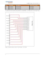
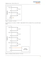
Страница 18: ...ct 17 No Connect Not Connected No Connect 18 No Connect Not Connected No Connect The following is an example wiring guide for a Cell Interface 12 channel with 12 cells and 8 cells Figure 5 Example wiring 12 cells in a Cell Interface 12 channel Installation Guide 2018 10 08 Rev 2 0 15 ...

Страница 19: ...tery Cell Connector Pin Assignment Pin Connection Description Connected to Device 1 CELL0 Bottom reference of Cell Interface Connect to negative terminal of the lowest cell Cell 1 2 CELL2 Cell 2 voltage sense Connect to positive terminal of Cell 2 3 CELL4 Cell 4 voltage sense Connect to positive terminal of Cell 4 Installation Guide 2018 10 08 Rev 2 0 16 ...

Страница 20: ... Cell 1 11 CELL3 Cell 3 voltage sense Connect to positive terminal of Cell 3 12 CELL5 Cell 5 voltage sense Connect to positive terminal of Cell 5 13 CELL7 Cell 7 voltage sense Connect to positive terminal of Cell 7 14 CELL9 Cell 9 voltage sense Connect to positive terminal of Cell 9 15 CELL11 Cell 11 voltage sense Connect to positive terminal of Cell 11 16 CELL13 Cell 13 voltage sense Connect to p...

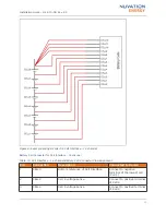
Страница 21: ...Figure 7 Example wiring 16 cells in a Cell Interface 16 channel Installation Guide 2018 10 08 Rev 2 0 18 ...

Страница 22: ...ection Description Connected to Device 1 CELL0 Bottom reference of Cell Interface Connect to negative terminal of the lowest cell Cell 1 2 No Connect Not Connected No Connect 3 CELL4 Cell 1 voltage sense Connect to positive terminal of the lowest cell Cell 1 4 No Connect Not Connected No Connect 5 CELL8 Cell 2 voltage sense Connect to positive terminal of Cell 2 Installation Guide 2018 10 08 Rev 2...

Страница 23: ...2 No Connect Not Connected No Connect 13 No Connect Not Connected No Connect 14 No Connect Not Connected No Connect 15 No Connect Not Connected No Connect 16 No Connect Not Connected No Connect 17 No Connect Not Connected No Connect 18 CELL16 Cell 4 voltage sense Connect to positive terminal of Cell 4 The following is an example wiring guide for a Cell Interface 12V 4 channel with 4 cells and 3 ce...

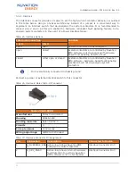
Страница 24: ...event of vibration failures Connect 10kΩ NTC thermistors to this connector Table 21 Temperature Sensors Molex Micro Fit 3 0 Connector Molex 43025 1600 Manufacturer Molex Incorporated Housing 43025 1600 Housing material Nylon UL94V 0 Circuits 16 Crimp terminal 43030 0002 Wire gauge range AWG20 24 stranded Table 22 Temperature Sensors Connector Pin Assignment Pin Connection Description Connected to ...

Страница 25: ...istor 9 TEMP1_R External Temperature Probe Input 1 10kΩ NTC Thermistor 10 TEMP2_R External Temperature Probe Input 2 10kΩ NTC Thermistor 11 TEMP3_R External Temperature Probe Input 3 10kΩ NTC Thermistor 12 TEMP4_R External Temperature Probe Input 4 10kΩ NTC Thermistor 13 TEMP5_R External Temperature Probe Input 5 10kΩ NTC Thermistor 14 TEMP6_R External Temperature Probe Input 6 10kΩ NTC Thermistor...

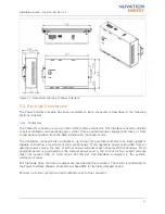
Страница 26: ...liant DIN rails The clips add an extra 19 6mm to the overall width of the Power Interface bringing it from 174 40mm to 194mm The clips also hold the module approximately 7mm away from the inside lip of the DIN rail Extra space should be provided around the module to allow for easy installation maintenance The Power Interface can contain high voltage signals It is possible to have signals 1250Vdc a...

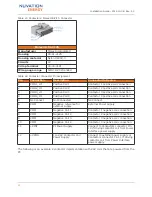
Страница 27: ...external contactor coils Each output is capable of sourcing a maximum of 2 8A continuously If coil operating power is provided from an external power source the sum of all four output currents must not exceed 5A continuous If coil operating power is provided from the internal power source the sum of all four output currents must not exceed 2 8A or 2 9A minus 31 7mA per Cell Interface connected in ...

Страница 28: ...No Connect Not Connected No Connect 6 COM Negative reference for external supply External Power Supply 7 COM Negative Coil 1 Contactor 1 negative coil connection 8 COM Negative Coil 2 Contactor 2 negative coil connection 9 COM Negative Coil 3 Contactor 3 negative coil connection 10 COM Negative Coil 4 Contactor 4 negative coil connection 11 VINT PI Power Supply Connect to Contactors connector Pin ...

Страница 29: ...xample 2 coil wiring The following is an example 4 contactor implementation that is powered from an external power supply Figure 13 Example externally powered 4 coil wiring Installation Guide 2018 10 08 Rev 2 0 26 ...

Страница 30: ...tects a fault closed either open or closed System contactors are controlled by Nuvation BMS software hardware based fault signaling mechanism will not de energize system contactors Pin 3 is electrically connected to chassis ground Connect a jumper or external interlock switch to this connector Table 26 Interlock Molex Micro Fit Connector Molex 43645 0300 Manufacturer Molex Incorporated Housing 436...

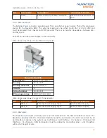
Страница 31: ...Housing 39 01 2025 Housing material Nylon UL94V 0 Circuits 2 Crimp terminal 39 00 0181 Wire gauge range AWG18 24 stranded Table 29 External Power Connector Pin Assignment Pin Connection Description Connected to Device 1 PWR_A External Power Supply Input External Power Supply 2 PWR_B External Power Supply Input External Power Supply 5 3 4 Stack Bus The Stack Bus connector provides power and communi...

Страница 32: ...Stack bus differential pair positive Stack Controller 6 COM Power return from Power Interface Stack Controller 5 3 5 Thermistor Contact Nuvation Energy for support if temperature compensation of the high current shunt is desired for your specific application Nuvation Energy can be contacted via support nuvationenergy com 5 3 6 Current Shunt The Current Shunt connector provides a current shunt inpu...

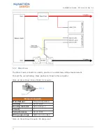
Страница 33: ...Connection Description Connected to Device 1 No Connect Not Connected No Connect 2 VSHUNT_REF Voltage reference for voltage measurement Load side of current shunt 3 VSHUNT_LOAD Differential voltage input Load side Load side of current shunt 4 VSHUNT_BAT Differential voltage input Battery side Battery side of current shunt An example high current shunt wiring diagram is shown below Installation Gui...

Страница 34: ...itive terminal to this connector Table 34 Stack Power Molex MiniFit Jr Connector Molex 39 01 4031 Manufacturer Molex Incorporated Housing 39 01 4031 Housing material Nylon UL94V 0 Circuits 3 Crimp terminal 39 00 0181 Wire gauge range AWG18 24 stranded Table 35 Stack Power Connector Pin Assignment Installation Guide 2018 10 08 Rev 2 0 31 ...

Страница 35: ...n Connected to Device 1 VBAT_POS Overall Stack Positive Connect to most positive terminal of the battery stack 2 No Connect Not Connected No Connect 3 No Connect Not Connected No Connect Installation Guide 2018 10 08 Rev 2 0 32 ...

Страница 36: ...tions on the Cell Interface and Ethernet and CAN interfaces on the Stack Controller It is acceptable as may be required in some cases for the battery stack to be ground referenced at some single point However a 24VRMS AC or 24VDC power supply connected to the Power Interface s External Power connection must be isolated from earth chassis ground with a working isolation voltage of at least 60Vrms f...

Страница 37: ...n the DC bus This is due to the industry standards for AC harmonics and EMC on the grid side which require the DC bus to help filter out the harmful emissions Unfortunately that means the battery cells and the Nuvation BMS experience extreme levels of noise The most harmful emissions on the DC bus are between the DC bus and earth This is due to the slew rate of the switching devices implemented in...

Страница 38: ...ounding scheme cannot be improved there are still a few techniques within the Nuvation BMS Battery area to try to decrease the amount of noise 6 3 1 DC Filtering A DC filter can be installed between the DC bus and the inverter or between each DC battery stack and the common DC bus in a multi stack system Schaffner FN 2200 is an example DC filter which has been known to decrease the amount of harmf...

Страница 39: ... 2 CAN485 pin 4 GPIO Out pin 5 GPIO In pin 1 2 3 or 4 6 3 3 Link Bus Power While the communication interface between the Stack Controller and the Cell Interface is a daisy chain the power supplied to the Cell Interface from the Stack Controller is a bus This results in the power twisted pair in the Link Bus cable carrying power up the entire length of the chain This provides a decent medium to cou...

Страница 40: ...Link Bus connector on the Stack Controller If a Factory Reset cable is unavailable connect an external 18 24V DC power supply to the Link Bus connector on the Stack Controller Pin 1 on the Link Bus connector is positive and Pin 2 is negative 4 Observe a blinking activity LED on the Stack Controller 5 Connect External Power to the Power Interface 6 Disconnect the Factory Reset cable from the Stack ...

Страница 41: ... time Nuvation Energy will make updates to the Nuvation BMS in response to changes in available technologies client requests emerging energy storage standards and other industry requirements The product specifications in this document therefore are subject to change without notice Copyright 2018 Nuvation Energy Installation Guide 2018 10 08 Rev 2 0 38 ...

Отзывы: