Pin
Connection
Description
Connected to Device
9
GPO_ISO3_B
Digital Output 3
External Equipment
10
No Connect
Not Connected
No Connect
3.3.5. GPIO-In
The GPIO-In connector provides four (4) general-purpose inputs. Four (4) independent detector
circuits are used, driven by an on-board +5V source. Each detector’s input is connected to its
corresponding pin, and paired with a COM reference pin per input. When switched on by an
external connection, each input will source about 12mA to COM.
Connect external equipment to this connector. Connect a pin to its corresponding COM to turn the
input on.
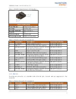
Table 9. GPI: Molex Micro-Fit 3.0 Connector
Molex 43025-0800
Manufacturer
Molex Incorporated
Housing
43025-0800
Housing material
Nylon UL94V-0
Circuits
8
Crimp terminal
43030-0002
Wire gauge range
AWG20-24 stranded
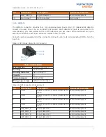
Table 10. GPI Connector Pin Assignment
Pin
Connection
Description
Connected to Device
1
COM
Power return from Stack Controller for
GPI0
External Equipment
2
COM
Power return from Stack Controller for
GPI2
External Equipment
3
COM
Power return from Stack Controller for
GPI3
External Equipment
4
COM
Power return from Stack Controller for
GPI4
External Equipment
5
GPI_ISO0_K
Input detector 0
External Equipment
6
GPI_ISO1_K
Input detector 1
External Equipment
7
GPI_ISO2_K
Input detector 2
External Equipment
8
GPI_ISO3_K
Input detector 3
External Equipment
Installation Guide - 2018-10-08, Rev. 2.0
8


