Isolation - Before commencing work make sure
that the unit and Nuaire control are electrically
isolated from the mains supply.
3.1 Equipment Access
Access for maintenance and inspection of the SQURBO XBOX
units is generally from the sides of the unit.
Once assembled and in position, sufficient free space must be
available adjacent to the unit for future inspection, maintenance,
component service, repair and replacement and connection of
services.
It is recommended that at least the unit width (vertically arranged
units XBV); or half the overall unit width (horizontally arranged
units XBH) + 100mm be allowed. (note – for units with a horizontal
layout (types XB/XBH), access is typically required to both sides
of the unit casing). Guidance may be found in Approved Document
F 2010.
3.2 Assembly of Equipment
SQURBO XBOX unit sections will be delivered to site in the number
of sections shown below.
Unit
No. of sections
S2 - S5 XBV
1
S6 and S7 XBV
1
S6 and S7 XBH
3
S8 / S9 / S10 XBV / XBH
3
For units with multiple sections, the sections consist of:
Supply fan (includes heater if included), extract
fan and heat exchanger.
Each Section will be labelled with the direction of air flow.
The direction convention must be observed during assembly. The
units may only be operated in their intended installation plane.
Twin (run & standby) extract fan versions are
supplied in the following arrangements;
Sizes S2T to S6T, vertically stacked XBV range: all the fans are
supplied within one single pre-assembled package as standard; the
standby fan is pre-wired to the Ecosmart control if fitted.
Sizes S8T with Ecosmart control (both horizontal and vertically
stacked): the standby fan is supplied bolted to the main fan and
connected to the control as standard.
Sectional units are supplied with matching internal connection
plates with a single bolt hole provided to each corner through
which the sections are bolted together. Unit access panels must be
removed to perform the assembly operation Plates will either have
clearance holes - or one face with a threaded insert and the other
with a clearance hole.
A sealing gasket should be applied as necessary to the mating
faces of the unit frames before bolting together.
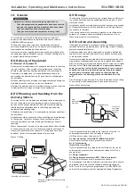
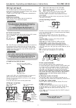
Figure 9: Section assembly plate.
Pipe-work connections to heating and / or cooling coils shall be
made to the appropriate standard, and the entire circuit tested for
tightness. Care must be taken not to over-tighten and distort
connections to coils.
2 Row LPHW Heating Coil Connection size
(standard LPHW unit)
S2 - S5 XBV
= 15 mm plain
S6 / S7 XBH/XBV
= 1.25 in BSP
S8 / S9 / S 10 XBH / XBV
= 2 in BSP
Connection sizes for other coil types are project specific.
Coils are tested during manufacture to 16 Bar (using dry
compressed air). Operation of standard equipment is rated at PN6,
if the intended system requires higher operating pressures; please
contact the Nuaire Technical department for advice.
Electrical connections to the unit shall be made in accordance with
the appropriate product (see below); and installation wiring
diagrams, and shall use appropriately sized and rated cables.
The unit rating label shows the maximum electrical load of the
equipment.
Connections to the unit may include three phase and single phase
supply connections, and a variety of control circuits.
Control circuit connections must be segregated (i.e. routed
separately) from power connections.
Only the prepared apertures in the unit casing may be used for
cable entry. Do not drill or cut the unit casing for this purpose.
The equipment must be earthed and earth-bonded.
Means of local isolation for maintenance purposes are generally
required and are specified and installed by others.
Weatherproof units
Weatherproof units in multiple sections will have sectional roof
components that must be fitted and sealed after the unit sections
are bolted together. (see figure 10). All necessary nuts, bolts,
washers and sealant are supplied with each unit and are normally
bagged and located within the fan section.
The equipment must not be exposed to the weather in an un-
assembled or partially assembled state. All ductwork, sealing and
assembly work must be completed before the unit can be considered
weather-proof.
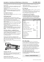
Figure 10: Weatherproof roof components.
3
08. 06. 18. Leaflet Number 671408
Installation, Operating and Maintenance Instructions
SQURBO XBOX
Use nuts and studs to join
plates of facing sections.
Example of weather kit for horizontal units 6 to 10 XBH, and
weather kit for stacked units 2 to 10 XBV.


