4
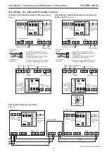
4.0 Wiring - for units with Ecosmart control
08. 06. 18. Leaflet Number 671408
Installation, Operating and Maintenance Instructions
SQURBO XBOX
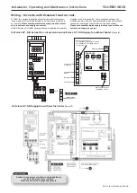
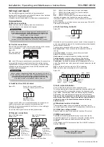
Unit sizes S2 - S5 with Ecosmart fan only control
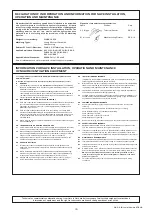
Figure 11:
230V-50Hz
Supply
Local isolator
(by others)
N
L
N
L
All inter-connections between circuit
boards, blowers and sensors are made
at the factory.
This diagram only shows the essential
field wiring points for clarity.
Damper Connections
Heat Demand
Signal
Run
Signal
Fault
Signal
Damper Connections
Run
Signal
Fault
Signal
NET
connections
for Ecosmart
devices
Min Max SL run
on
Trickle Test
0
1
Link wire see note*
ES-CO2
Connection
BMS
Input
Signal
0-1
0V
0V
Ecosmart
Pwr
Standby
Fan 1
Fan 2
Heating
Cooling
Fault
Frost
TX
RX
Extract
N
E
L
SL
DP
CL
N
RET
Heat
Demand Run Fault
NET
connections
for Ecosmar
t
devices
Min Max SL run
on
T ric
kle
T es
t
0
1
Link wire see note*
ES-CO2
Connection
BMS
Input
Signal
0-1
0V
0V
Ecosmart
Pwr
Standby
Fan 1
Fan 2
Heating
Cooling
Fault
Fr
ost
TX
RX
Supply
N
E
L
SL
DP
CL
N
RET
Heat
Demand
*Remove link wire if switched live signal,
an enabler or BMS signal is connected.
Run
Fault
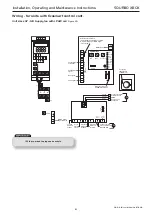
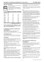
Unit sizes S2 - S5 with Ecosmart fan and electric
heater control
Figure 12:
230V-50Hz
Supply
Local isolator
(by others)
N
L
N
L
All inter-connections between circuit
boards, blowers and sensors are made
at the factory.
This diagram only shows the essential
field wiring points for clarity.
Damper Connections
Heat Demand
Signal
Run
Signal
Fault
Signal
Damper Connections
Run
Signal
Fault
Signal
NET
connections
for Ecosmart
devices
Min Max SL run
on
Trickle Test
0
1
Link wire see note*
ES-CO2
Connection
BMS
Input
Signal
0-1
0V
0V
Ecosmart
Pwr
Standby
Fan 1
Fan 2
Heating
Cooling
Fault
Frost
TX
RX
Extract
N
E
L
SL
DP
CL
N
RET
Heat
Demand Run Fault
NET
connections
for Ecosmar
t
devices
Min Max SL run
on
T ric
kle
T es
t
0
1
Link wire see note*
ES-CO2
Connection
BMS
Input
Signal
0-1
0V
0V
Ecosmart
Pwr
Standby
Fan 1
Fan 2
Heating
Cooling
Fault
Fr
ost
TX
RX
Supply
N
E
L
SL
DP
CL
N
RET
Heat
Demand
*Remove link wire if switched live signal,
an enabler or BMS signal is connected.
Run
Fault
Heater Temperature
Setting
C
o
15
20
25
30
NET
connections
for Ecosmart
devices
Min Max SL run
on
Trickle Test
0 1
ES-CO2
Connection
BMS
Input
Signal
0-1
0V
0V
Ecosmart
Pwr
Standby
Fan 1
Fan 2
Heating
Cooling
Fault
Frost
TX
RX
Extract
N
E
L
SL
DP
CL
N
RET
Heat
Demand Run Fault
NET
connections
for Ecosmart
devices
Min Max SL run
on
Trickle Test
0 1
ES-CO2
Connection
BMS
Input
Signal
0-1
0V
0V
Ecosmart
Pwr
Standby
Fan 1
Fan 2
Heating
Cooling
Fault
Frost
TX
RX
Extract
N
E
L
SL
DP
CL
N
RET
Heat
Demand Run
Fault
N
E
L
SL
Fault
Client
wiring
EXTRACT FAN
STANDBY FAN
RELAY STANDBY
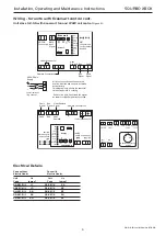
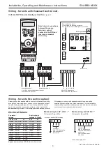
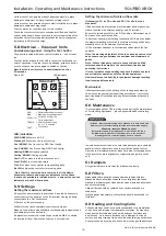
S2T to S5T Twinfans all variants
Figure 13:


