


05. 11. 20. Leaflet Number 671828
BOXER BPS
ECOSMART CONNECT CONTROL (CO)
7
3.3 Unit Protection
4.2 Air Leakage
4.3 Unit Joints
3.4 Unit Storage
4.0 ERECTION & ASSEMBLY
4.1 Unit Location
Unless otherwise specified, unit sections will be delivered to site covered in
“shrink wrap” polythene, which should provide a more than adequate level of
protection against inclement weather.
Should alternative methods of unit protection be required (i.e. timber, Corex,
or flame retardant materials), Nuaire Limited should be notified of the specific
requirements at the pre- contract stage. Waste must be disposed of by a
registered waste carrier in accordance to national regulations.
Loading, transportation, off loading and site positioning can cause the air
handling unit structures to move, therefore panel seals will not always remain
fully intact.
It is inevitable that in such cases, re-sealing of the units panels and joints may
have to be carried out on site for the air-handling units to achieve the required
leakage classification.
Door locking mechanisms may also have to be adjusted.
Nuaire cannot be held responsible for the units failing a site leakage
test if the above have not been carried out correctly.
After unwrapping, temporarily remove the rubber weatherproof cover strip and
M10 base frame bolts from any modules and store in a safe location for later
use.
Apply the sealing gasket as necessary to the mating faces of the unit frames.
Typically the sealing gaskets are pre-fitted to the heat exchanger module;
ancillary modules will be provided with a roll of sealing gasket for on-site fitting.
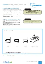
Make the unit joints in the following order:
•
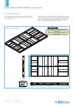
Left and right hand side M10 bolts between the modules’ base frames
(See Figure 5).
•
Left and right hand side M6 Lower 3 axis alignment clamps (see Figure 6).
•
Left and right hand side M6 Middle 3 axis alignment clamps.
•
Left and right hand side M6 Upper 3 axis alignment clamps.
Finally, where the roofs of the two sections meet, the rubber weatherproof cover
strip removed earlier must be applied to seal the seam (see Figure 7).
Air leakage, air blow marks to the unit casings and unacceptable noise levels
could result if the correct installation procedures are not employed.
The equipment must be stored in a dry, internal location. Ductwork connection
apertures should be sealed against the ingress of dust, water and vermin.
Note that units that are intended for external locations are generally not fully
weatherproofed until their installation, including ductwork connections, is
complete.
If the storage period is to exceed two months, contact Nuaire for guidance
on the appropriate ‘mothballing’ procedures. Do not stack units, modules or
components.
Installation must be carried out by competent personnel, in accordance with
good industry practice, with the appropriate authority and in conformance with
all statutory and governing regulations.
The unit should stand upright and level on the floor, foundation or supporting
steelwork which should be rigid, flat and level and should be capable of
supporting the weight of the unit including water or refrigerant in the coils.
Nuaire Limited takes no responsibility for the coordination of support.
To prevent possible reintroduction of contaminated air through the outside air
intake, the unit should be located away from building flue stacks or exhaust
ventilators.
Once assembled and in position, sufficient free space must be available adjacent
to the unit for future inspection, maintenance, component service, repair and
replacement and connection of services.
It is recommended that at least half the unit width (horizontally arranged
units) + 100mm be allowed. A minimum of 600mm is required for regular
maintenance.
Motors are fitted with ‘sealed for life’ bearings and do not require any
lubrication. All dampers should be rotated and lubricated as necessary.
3.5 Lubrication
IMPORTANT
Sufficient clearance for U-traps on condensate drain and
overflow connections should also be considered by the
purchaser.
IMPORTANT
Prior to making the unit joints, you must ensure the base frames of
adjoining modules are contiguous (fully touching) along the width of
the unit. Failure to do so can result in deformation of the unit frame
when using the three axis alignment clamps.
Figure 5. M10 base frame bolt.
Figure 6. Three axis alignment clamp.
Содержание ecosmart CONNECT BPS
Страница 19: ...05 11 20 Leaflet Number 671828 BOXER BPS ECOSMART CONNECT CONTROL CO 19...
Страница 21: ...05 11 20 Leaflet Number 671828 BOXER BPS ECOSMART CONNECT CONTROL CO 21...
Страница 25: ...05 11 20 Leaflet Number 671828 BOXER BPS ECOSMART CONNECT CONTROL CO 25...
Страница 33: ...05 11 20 Leaflet Number 671828 BOXER BPS ECOSMART CONNECT CONTROL CO 33...
Страница 45: ...05 11 20 Leaflet Number 671828 BOXER BPS ECOSMART CONNECT CONTROL CO 45...
Страница 55: ...05 11 20 Leaflet Number 671828 BOXER BPS ECOSMART CONNECT CONTROL CO 55 NOTES...


