


6
22. 02. 22. Document Number 611280
Nuaire | Western Industrial Estate | Caerphilly | CF83 1NA | nuaire.co.uk
DAVE Extract (DE)
Installation Manual
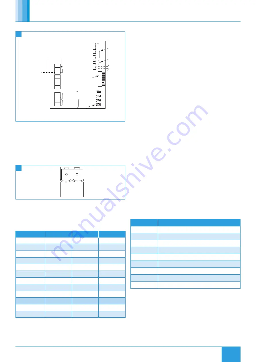
6.5 Control Panel
Volt Free
0.5A inductive
Contact
RUN signal
5A resistive
Volt Free
Contact
FAULT signal
N
L
SL
DP
RUN
FA
U
LT
CL
N
RET
Switc
if a BMS is connected.
Also remove link if an
enabling device is
connected in the 'NET'
Remove this link wire if
a switched live signal is
connected to terminal SL
NOTE: Also remove link
h live signal
(if required)
NET connections for
No user
ECOSMART devices
connections
connections
CO2 sensor
0
ECOSMA
RT NET
+ve signal
from BMS
Ribbon cable
to commissioning
box
230V 1ph 50Hz supply / 220V 1ph 60Hz supply
11
PCB Details
6.5.1 BMS Input Signals
The BMS connection is made with a plug-in connector via the socket. To
ensure the connection is made only by suitably qualified and authorised
personnel the plug is not supplied.
Plug-in BMS connector is available from:
R S Components, Part No. 403-875 or
Farnell, Part No. 963-021
0 - 10V
0V
BMS
12
BMS Connection
Reversal of the BMS connection will damage the control.
The system’s response to a 0-10V dc BMS signal is given in the table
below.
Note the BMS signal will override any sensors and user
control connected in the system. The voltage tolerance is +/-
125mV and is measured at the fans terminal.
Ventilation
Cooling mode * Heating mode *
Local Control
0.00
-
-
OFF / Trickle
0.25
-
-
Speed 1
0.50
0.75
1.00
Speed 2
1.50
1.75
2.00
Speed 3
2.50
2.75
3.00
Speed 4
3.50
3.75
4.00
Speed 5
4.50
4.75
5.00
Speed 6
5.50
5.75
6.00
Speed 7
6.50
6.75
7.00
Speed 8
7.50
7.75
8.00
Speed 9
8.50
8.75
9.00
Speed 10
9.50
9.75
10.00
*Only available on relevant unit
7.0 MAINTENANCE
Isolation - Before commencing work, make sure that the unit and
Nuaire control are electrically isolated from the mains supply.
It is important that maintenance checks are recorded and that the
schedule is always adhered to, in all cases, the previous report should
be referred to.
Motors are fitted with sealed for life bearings and do not require any
lubrication.
7.1 Routine Maintenance
•
Remove the top or the bottom cover and carefully clean out the
interior as necessary.
•
Check all parts for security and that the impeller rotates freely,
taking care not to disturb the balance.
•
The filter (where applicable) will require cleaning on a regular
basis. The frequency of the cleaning operation will depend on the
site conditions.
•
Ensure all control components are secure and clean.
•
Refit the cover.
7.2 Annually
•
All electrical terminals within the unit should be tightened.
•
Check all earth connections.
7.3 Dirty Filter Alarm (Extended Case Models Only)
Units pre fitted with a panel air filter are equipped with an visual Red
LED alarm on the side of the control. The pressure switch is pre set at
150pa and positioned within the unit and accessed via the removable
top or bottom panel. If required, the alarm signal can be positioned to
another area by others using the pre fitted terminal block - A volt free
relay must be used between the control and customer wiring.
LED On
= Pressure exceeds the maximum allowable final pressure drop.
Replacement filter part numbers are shown below.
7.4 G3 Filter Replacement (Extended Case Models Only)
Unit
Replacement Part Number
DE1A-ES
D1A-G3FILTERKIT
DE2A-ES
D2A-G3FILTERKIT
DE2HA-ES
D2HA-G3FILTERKIT
DE3A-ES
D3A-G3FILTERKIT
DE4A-ES
D3A-G3FILTERKIT
DE4HA-ES
D4HA-G3FILTERKIT
DE5A-ES
D5A-G3FILTERKIT
DE6A-ES
D6A-G3FILTERKIT
DE7A-ES
D7A-G3FILTERKIT