


Isolation - Before commencing work make sure that the
unit, switched live and Nuaire control are electrically
isolated from the mains supply and switched live supply.
7
09. 06. 16. Leaflet Number 671684
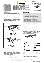
Installation and Maintenance
The WM1 Wall Mounted Range of Units
The filters fitted inside the unit are protected with a
plastic film. Prior to commissioning remove the covers
(figs 14/15), take off the film and replace.
Filter covers
Figure 14. Removing the two filter covers on the front panel of
the unit.
Filter being
removed
Filter cover
Figure 15.The filters can be removed by pulling on the black tab
on the visible end of the filters.
Figure 13. Detail of unit control
on front panel.
Normal Mode
Supply Fan Fault
Extract Fan Fault
Boost
Frost Protection
Filter Change
Summer Bypass
060923
Extract
Fan
Supply
Fan
Run on
Trickle
Boost
Trickle
Boost
Extract
Fan
Supply
Fan
Run on
Trickle
Boost
Trickle
Boost
Summer Bypass (AB unit only).
6.0 Commissioning
1. For the required air flow rates please refer to the design
specification for the property, follow 2.4, or refer to building
regulations ADF 2010.
2. The unit is supplied with independent control for both normal
and boost airflows. (see fig. 13).
3. Correct commissioning is essential to ensure the ventilation air
flowrates are met. It also ensures the unit is not over ventilating
and causing excessive power consumption.
4. Commissioning should be carried out in accordance with building
regulations document “Domestic ventilation compliance guide”.
www.planningportal.gov.uk/building regulations/approved
documents/partf/associated
A calibrated moving vane anemometer and hood will be required
to carry out commissioning.
5. Adjustment valves should be locked in place to prevent further
adjustment.
6. Once commissioned the home owner / tenant should be informed
that the unit should not be adjusted as it will have a detrimental
effect on the indoor air quality and could result in condensation
and mould growth. The label covering the control has an adhesive
panel which should be removed post commissioning to prevent
tampering.
7. The trickle flow rate is limited to never exceed the boost rate,
when commissioning the boost rate should always be set first.
7.0 Status Indication
The status of the unit is indicated by a series of LED’s on the front
cover. The varients are listed below.
8.0 Thermal Bypass (Non AB models)
In the event of excessive outside temperatures, and to help prevent
over-heating, the supply fan will automatically reduce to a trickle
speed. Under these circumstances additional ventilation measures may
be required e.g. open windows or trickle vents (if fitted).
9.0 Maintenance/Cleaning
We recommend that the two G3 fiters are inspected after 6 months,
and replaced every 12 to 18 months. The filters can be removed from
the unit by removing the two filter covers on the front panel of the
unit. Take hold of the two circular tabs either end of the filter covers
and pull out.
The filter can now be extracted by pulling the removal loop on the
front edge of the filter. Once the filters have been inspected return
or replace them as necessary. Inspect the heat exchanger every
5 years. Generally check for damage and security of components.
Refit cover.


