Nuaire Group BPC MRXBOX95-WM1 Скачать руководство пользователя страница 6

For good EMC engineering practice, any sensor cables or

switched live cables should not be placed within 50mm of

other cables or on the same metal cable tray as other cables.

6

09. 06. 16. Leaflet Number 671684

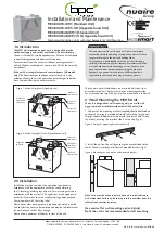
Installation and Maintenance

The WM1 Wall Mounted Range of Units

5.0  Electrical Connection

Please note: the electrical connection of the unit must be be carried
out by a qualified electrician.

The unit is supplied with a flexible cord for connection to the mains
supply.

Electrical details:-

Voltage:

240V  1ph  50Hz

Consumption:  75W - 0.6 Amp 

Fuse rating: 

3 Amp

NOTE This unit must be earthed.

The four core cable from the mains power supply should be 
connected to a fixed wiring installation, via a fused isolator, in
accordance with current IEE wiring regulations.

5.1 Optional Connections

Ecosmart control 

(see figure 10) The IDC plug-in connectors are

provided for the connection of compatible sensors. 

NOTE: Do not run the data cable in the same conduit as the mains
cable and leave a 50mm separation with any power cables.

Fuse 2A

MAINS
230V
50Hz

Room
light

Light 

switch 

(Double 

Pole)

N

L

Fuse 2A

MAINS
230V
50Hz

Room
lights

Light 

switches 

(Double 

Pole)

N

L

3 Pole
isolator

3 Pole
isolator

Kitchen switch

Kitchen switch

Green/yellow

Blue

Brown

Black

Supply cord
from unit

Green/yellow

Blue

Brown

Black

Supply cord
from unit

Unit serving kitchen and bathroom

Figure 11. 

Unit serving kitchen and two bathrooms

Figure 12. 

TEMP

Connection to 
Remote Fail 
Indicator Ref: 
MRXBOX95LH-RFI
(Optional)

24V  0V   SW

FAN 1

FAN 2

Internal wiring

Run-on  Trickle  Boost  Trickle  Boost  

Connection to 
Ecosmart
sensors

ECOSMART NET

Figure 10.

Note: Wiring is for reference 
purposes only as the 
connections in fig. 10 
are factory fitted. 
The unit is pre-wired with 
a 2 metre fly lead. 

5.2  Optional Controls 

For further information contact Nuaire on 029 2085 8400.

Содержание BPC MRXBOX95-WM1

Страница 1: ... the pre drilled holes in the bracket and install with screws by others ensuring the interlock side is at the top fig 3 Figure 3 Fixing the mounting bracket to the wall 2 Install the unit on the wall by ensuring the bracket fixed to the rear of the unit interlocks over the wall mounted bracket fig 4 Figure 4 Mounting the unit on the wall mounted bracket Note Care must be taken to ensure the unit i...

Страница 2: ...Figure 5 Typical example of a cupboard mounted unit Standard unit fixed to a block work wall Option 2 Wall Mounting If it is not practical to use a solid wall the MVHR unit should be fixed to a stud partition with a 25mm minimum thickness MDF panel solidly fixed behind the plasterboard If fixing to a stud wall the MDF panel should extend width wise over a minimum of 3 vertical studs with centres o...

Страница 3: ...pt to a minimum A minimum distance of 300mm between the appliance and any bends in ductwork is recommended Ideally 150mm diameter or 204 x 60mm rectangular ducting should be used Refer to dwelling design drawing figure 9a and 9b on page 5 for further information Ducting joints must be sealed with silicone type sealant and shall be adequately and reliably fixed to the appliance 2 6 Ventilation flow...

Страница 4: ...ly as an alternative the purge ventilation provisions given in ADF 2010 can be used where security is not an issue In this case minimum high extract rate for the sanitary accommodation should be omitted from the step 2 calculation Step 3 The required airflow rates are as follows n the maximum whole dwelling extract ventilation rate e g boost should be at least the greater of step 1 and step 2 Note...

Страница 5: ...upply duct Air supply to lounge via Air Valve in ceilings Extract air from kitchen bathroom via Air Valve in ceilings Air supply to bedrooms via Air Valve in ceilings Top of ceiling void Top of ceiling void Nuaire wall mounted unit Air supply to bedrooms via Air Valve in ceilings Nuaire wall mounted unit MVHR DRAIN Condensate drain uninsulated drain pipe with min 5o fall running to SVP MVHR DRAIN ...

Страница 6: ...ure 10 The IDC plug in connectors are provided for the connection of compatible sensors NOTE Do not run the data cable in the same conduit as the mains cable and leave a 50mm separation with any power cables Fuse 2A MAINS 230V 50Hz Room light Light switch Double Pole N L Fuse 2A MAINS 230V 50Hz Room lights Light switches Double Pole N L 3 Pole isolator 3 Pole isolator Kitchen switch Kitchen switch...

Страница 7: ...ngportal gov uk building regulations approved documents partf associated A calibrated moving vane anemometer and hood will be required to carry out commissioning 5 Adjustment valves should be locked in place to prevent further adjustment 6 Once commissioned the home owner tenant should be informed that the unit should not be adjusted as it will have a detrimental effect on the indoor air quality a...

Страница 8: ...ectrically competent person When ordering spare parts please quote the serial number of the unit and the ARC number of the purchase if possible This information will be available on the fan label 11 0 Warranty The 5 year warranty starts from the day of delivery and includes parts and labour for the first year and parts only for the remaining 4 years This warranty is conditional on planned maintena...

Страница 9: ...lings assessed under The Building Regulations 2010 specifically SAP 2009 and Approved Documents L and F Completion of this document is therefore only required for dwellings assessed by SAP 2005 Customer Details Customer Name Address Telephone Number Date of Installation Name of Lead Contractor Design Project Number It should be noted that this guidance is not intended to replace product manufactur...

Страница 10: ...or to overcome particular obstructions If flexible ducting has been used has it been pulled taut to minimise system resistance Has the number of duct bends been minimised to ensure adequate air flow and least resistance Bends should have a minimum radius at least the same as the diameter of the ducting used Refer to Figure 1 if using flexible ducting Have the fans and ducting placed in unheated vo...

Страница 11: ...ry unit been fixed to a stable element of the building fabric e g wall or floor using manufacturer recommended supplied fixing brackets Has the condensation drain been fitted and the pipe insulated Have approved acoustic anti vibration mountings been used Note Special attention is needed to avoid transmission and stress to duct joints Has the unit been installed in a position that will permit acce...

Страница 12: ... or N A Has the rating label been verified to establish suitability for the installation strategy and whether an earth is required e g voltage class I or II product status Has a local isolator been provided to enable the unit to be isolated for maintenance purposes Has the unit been fused in accordance with its power rating SECTION 2 COMMISSIONING GUIDANCE ...

Страница 13: ...ution grilles been locked where possible to minimise unapproved occupant adjustment Figure 3 Ensure all external and internal windows and doors are closed Set fan speed using manufacturer data table Set normal daytime air flow on extract points starting at location furthest from unit Set normal daytime air flow on input points starting at location furthest from unit Step 1 Step 2 Step 3 Step 4 Ste...

Страница 14: ...he customer been advised that opening windows is not recommended during normal use in order to ensure the energy efficient operation and performance of the balanced system Has the customer been advised not to seal natural air flows from room to room e g avoid door seals and thick pile carpets Has the customer been advised not to alter settings post commissioning Has the customer been advised to cl...

Отзывы: